background image

3.

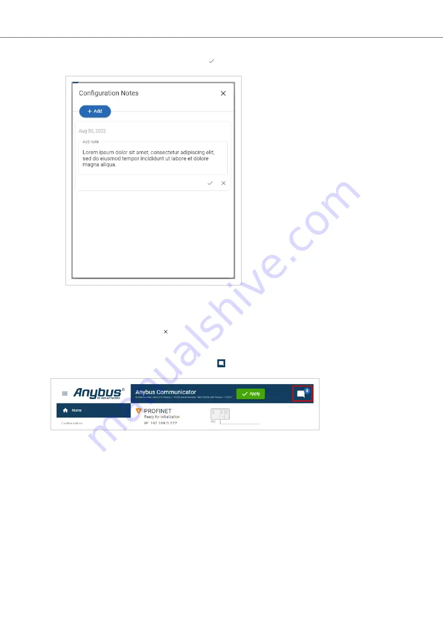
Write your configuration note and click accept 

.

Figure 32. Write a configuration note

The configuration note is added to the list.

4.

To close the window, click close  .

6.9.2. View and Edit Configuration Notes

To view and/or edit a note, click on the comments icon  .

Figure 33. Example: The comment icon indicates that there are three added notes

The configuration notes are listed in the Configuration Note window.

Anybus

®

 Communicator

 - Modbus TCP Server to PROFIBUS DP Device

Configuration Notes

Page 38 of 60

SCM-1202-201 Version 1.0

Содержание Anybus Communicator ABC4018

Страница 1: ...Anybus Communicator Modbus TCP Server to PROFIBUS DP Device USER MANUAL SCM 1202 201 Version 1 0 Publication date 2022 08 31 ENGLISH ...

Страница 2: ...t and because of the many variables and requirements associated with any particular implementation HMS Networks cannot assume responsibility or liability for actual use based on the data examples or illustrations included in this document nor for any damages incurred during installation of the product Those responsible for the use of the product must acquire sufficient knowledge in order to ensure...

Страница 3: ...PROFIBUS Network 11 5 5 Rotary Switch Settings 12 5 5 1 Rotary Switches Default Setting 12 5 5 2 Set a Node Address with Rotary Switches 13 5 6 Connect to Power 17 5 7 Security Switch 18 5 8 Lock the Cables 20 5 9 DIN Rail Demount 21 6 Communicator Configuration 23 6 1 Connect the Communicator 23 6 2 Access the Built In Web Interface From HMS IPconfig 24 6 3 Access the Built In Web Interface From ...

Страница 4: ...6 9 1 1 Export Configuration 46 9 1 2 Import Configuration 47 9 2 Clear and Revert Configuration 48 9 3 Firmware Management 49 9 3 1 View the Firmware Version 49 9 3 2 Firmware and Configuration Compatibility 49 9 3 3 Firmware File Validation 49 9 3 4 Update Firmware 50 10 Troubleshooting 51 10 1 Diagnostics 51 10 1 1 I O Data 51 10 1 2 Event Log 52 10 2 Reset to Factory Settings 53 10 3 Firmware ...

Страница 5: ... References and Links Cross reference within this document Document Conventions page 1 External link URL www anybus com Safety Symbols DANGER Instructions that must be followed to avoid an imminently hazardous situation which if not avoided will result in death or serious injury WARNING Instructions that must be followed to avoid a potential hazardous situation that if not avoided could result in ...

Страница 6: ... or operation TIP Helpful advice and suggestions 1 3 Trademarks Anybus is a registered trademark of HMS Networks All other trademarks are the property of their respective holders Anybus Communicator Modbus TCP Server to PROFIBUS DP Device Trademarks Page 2 of 60 SCM 1202 201 Version 1 0 ...

Страница 7: ...ION Ensure that the power supply is turned off before connecting it to the equipment CAUTION This equipment contains parts that can be damaged by electrostatic discharge ESD Use ESD prevention measures to avoid damage CAUTION To avoid system damage the equipment should be connected to ground IMPORTANT Using the wrong type of power supply can damage the equipment Ensure that the power supply is con...

Страница 8: ...rface can be accessed from the following standard web browsers Google Chrome Microsoft Edge Mozilla Firefox 3 3 Mechanical Tools and Equipment Have the following tools available Flat head screwdriver size 5 5 mm Needed when removing the Communicator from DIN rail 3 4 Support and Resources For additional documentation and software downloads FAQs troubleshooting guides and technical support please v...

Страница 9: ...e you can set a static IP address within the same IP address range as the Communicator IP address on the computer accessing the Communicator built in web interface NOTE IPconfig is only available for Windows 3 6 Third Party Software Applications Microsoft Excel or equivalent software application that supports the Office Open XML Workbook xlsx file format Needed to open and read the Event log file ...

Страница 10: ...connected to a Modbus TCP network and a Master device connected to a PROFIBUS network The Master device can for example be a PLC control system or a Gateway The Communicator main task is to transfer cyclic I O data between the two networks Anybus Communicator Modbus TCP Server to PROFIBUS DP Device About Anybus Communicator Page 6 of 60 SCM 1202 201 Version 1 0 ...

Страница 11: ...es input data Output Data The Output data area is read written by the Modbus TCP The Communicator can handle up to 1500 bytes output data 4 3 Data Integrity A snapshot of the process data buffer between the Modbus TCP PROFIBUS Client and the server interface is used during the operation of executing all the transactions within one cycle When the cycle is completed the process data available on the...

Страница 12: ...Ds E Configuration port F Modbus TCP port x 2 G PROFIBUS DSUB connector H Cable tie mount I Laser engraved connectors designation J Security switch K Factory reset button L Laser engraved label with product information M DIN rail locking mechanism Anybus Communicator Modbus TCP Server to PROFIBUS DP Device Installation Page 8 of 60 SCM 1202 201 Version 1 0 ...

Страница 13: ...e rail and that the rail is properly grounded Figure 4 Attach the Communicator on the DIN rail To attach the Communicator on the DIN rail 1 Insert the upper end of the DIN rail clip into the DIN rail 2 Push the bottom of the DIN rail clip into the DIN rail DIN Rail Mounting Anybus Communicator Modbus TCP Server to PROFIBUS DP Device SCM 1202 201 Version 1 0 Page 9 of 60 ...

Страница 14: ...ption 1 TD 2 TD 3 RD 4 Not used 5 Not used 6 RD 7 Not used 8 Not used To Do Next Connect the Communicator to the PROFIBUS network set the node address on the rotary switches and connect to power Check LED status refer to Communicator LED Indicators Anybus Communicator Modbus TCP Server to PROFIBUS DP Device Connect to Modbus TCP Network Page 10 of 60 SCM 1202 201 Version 1 0 ...

Страница 15: ...ed 3 Line B 4 RTS 5 GND Bus 6 5 V Bus Out 7 Not used 8 Line A 9 Not used Housing PE To Do Next Connect the Communicator to the Modbus TCP network set the node address on the rotary switches and connect to power Check LED status refer to Communicator LED Indicators Connect to PROFIBUS Network Anybus Communicator Modbus TCP Server to PROFIBUS DP Device SCM 1202 201 Version 1 0 Page 11 of 60 ...

Страница 16: ...s Default Setting By default the value on the three rotary switches are set to 000 Figure 7 Rotary switches default setting 000 Anybus Communicator Modbus TCP Server to PROFIBUS DP Device Rotary Switch Settings Page 12 of 60 SCM 1202 201 Version 1 0 ...

Страница 17: ...tting is 000 The node address values are set in hexadecimal hex Minimum value is 00 Each node address may only occur once in the network The node address is read from the center rotary switch x16 to the front rotary switch x1 The rear rotary switch is not used ensure that it is set to 0 Rotary Switch Settings Anybus Communicator Modbus TCP Server to PROFIBUS DP Device SCM 1202 201 Version 1 0 Page...

Страница 18: ...gure 8 Disconnect Communicator from power Procedure Use a screwdriver to change the rotary switch position Ensure that the rotary switches engage correctly Anybus Communicator Modbus TCP Server to PROFIBUS DP Device Rotary Switch Settings Page 14 of 60 SCM 1202 201 Version 1 0 ...

Страница 19: ...ary switch B to 1 hex 3 Set the front rotary switch C to 2 hex The center rotary switch B 1 hex 1 dec and the front rotary switch C 2 hex 2 dec The node address expressed in decimal numbers is therefore 16 x 1 2 18 Rotary Switch Settings Anybus Communicator Modbus TCP Server to PROFIBUS DP Device SCM 1202 201 Version 1 0 Page 15 of 60 ...

Страница 20: ...de address is active as soon as the Communicator is powered on NOTE Changing the address settings on the rotary switches during operation is ignored For a new address to take effect power cycle the Communicator Anybus Communicator Modbus TCP Server to PROFIBUS DP Device Rotary Switch Settings Page 16 of 60 SCM 1202 201 Version 1 0 ...

Страница 21: ...to power 1 Insert the cable wires to the terminal block and tighten the wire clamp screws Power port Pin Description 1 12 30 VDC Power Connector 2 Ground GND 3 Functional Earth FE 2 Connect the terminal block to the Communicator 3 Connect the Communicator to a power supply 4 Turn on the power supply To Do Next Check LED status refer to Communicator LED Indicators Connect to Power Anybus Communicat...

Страница 22: ...ured via the PLC is still available To Lock and Unlock the Security Switch Figure 11 Security switch in locked and unlocked position Use a pointed object such as a ballpoint pen To lock the security switch push the toggle towards the Communicator front To unlock the security switch push the toggle towards the Communicator back Anybus Communicator Modbus TCP Server to PROFIBUS DP Device Security Sw...

Страница 23: ...en the security switch is in its locked position the security switch status LED turn solid green unlocked position the security switch status LED is turned off Security Switch Anybus Communicator Modbus TCP Server to PROFIBUS DP Device SCM 1202 201 Version 1 0 Page 19 of 60 ...

Страница 24: ...Figure 13 Lock the cables To strain relieve the cables place a cable tie in the holder and lock the cables Anybus Communicator Modbus TCP Server to PROFIBUS DP Device Lock the Cables Page 20 of 60 SCM 1202 201 Version 1 0 ...

Страница 25: ...at blade screwdriver size 5 5 mm available Procedure Remove the Communicator from the DIN Rail 1 Insert the screwdriver into the Communicator DIN rail locking mechanism 2 To unlock the Communicator DIN rail locking mechanism turn the screwdriver clockwise Figure 14 Unlock the Communicator DIN Rail Demount Anybus Communicator Modbus TCP Server to PROFIBUS DP Device SCM 1202 201 Version 1 0 Page 21 ...

Страница 26: ...e DIN rail locking mechanism while you unhook the Communicator from the DIN rail Figure 15 Unhook the Communicator Anybus Communicator Modbus TCP Server to PROFIBUS DP Device DIN Rail Demount Page 22 of 60 SCM 1202 201 Version 1 0 ...

Страница 27: ...etwork Network 1 Modbus TCP Network 2 PROFIBUS Connect to PC and Power 1 Connect an Ethernet cable between the Communicator and your PC 2 Connect the Communicator to a power supply Communicator Configuration Anybus Communicator Modbus TCP Server to PROFIBUS DP Device SCM 1202 201 Version 1 0 Page 23 of 60 ...

Страница 28: ...port Port 3250 UDP is open in your PC Windows Firewall NOTE Ensure that the security switch is unlocked HMS IPconfig cannot configure the Communicator if the security switch is locked Procedure 1 Install HMS IPconfig on your PC 2 Open HMS IPconfig HMS IPconfig automatically starts scanning for compatible and active HMS devices Found HMS devices are added to the device list 3 To open the settings p...

Страница 29: ...e click Communicator Result You are redirected to the Communicator built in web interface Home page Access the Built In Web Interface From HMS IPconfig Anybus Communicator Modbus TCP Server to PROFIBUS DP Device SCM 1202 201 Version 1 0 Page 25 of 60 ...

Страница 30: ...change to a static IP address on your computer internet access may be lost Procedure 1 On the PC accessing the Communicator built in web interface set a static IP address within the same IP address range as the Communicator IP address 2 Open a web browser 3 Click to select the Address bar and enter the Communicator IP address 4 To open the built in web interface Home page press Enter Anybus Commun...

Страница 31: ...e the network settings for the PROFIBUS network I O configuration Configure input and output data sizes and endian conversion Files firmware Save settings in a configuration files upload configuration files and upgrade firmware Diagnostics Monitor and troubleshoot the Communicator Support Contains Communicator product information Anybus contact information link to Anybus support website and produc...

Страница 32: ...r Figure 17 IP Settings DHCP enabled By default the IP settings are provided by the high level network DHCP server The DHCP enabled checkbox is selected Anybus Communicator Modbus TCP Server to PROFIBUS DP Device Modbus TCP Settings Page 28 of 60 SCM 1202 201 Version 1 0 ...

Страница 33: ...dress The Modbus TCP network Gateway address in IPv4 dot decimal notation If there is no gateway available set the Gateway address to 0 0 0 0 Primary DNS server The Modbus TCP network Primary DNS in IPv4 dot decimal notation Secondary DNS server The Modbus TCP network Secondary DNS in IPv4 dot decimal notation DHCP Enabled If you change a value and click Refresh the value is reset to the last appl...

Страница 34: ...bus TCP connection may be idle before it is closed by the Communicator The default value is 60 seconds Process Data Active Timeout Specify the maximum allowed time between two incoming messages in steps of 10 ms If this time is exceeded the high level network is considered to be offline The data sent to the sub network is frozen A value of 0 disables this feature i e the high level network can nev...

Страница 35: ...ction may be idle before it is closed by the Communicator The default value is 60 seconds Process Data Active Timeout Specify the maximum allowed time between two incoming messages in steps of 10 ms If this time is exceeded the high level network is considered to be offline The data sent to the sub network is frozen A value of 0 disables this feature i e the high level network can never go offline...

Страница 36: ... sizes for the networks deselect the Same I O sizes for both networks checkbox Endian Swap Big endian The big endian format places the most significant byte of the data at the byte with the lowest memory address Little endian The little endian format places the least significant byte of the data at the byte with the lowest memory address Anybus Communicator Modbus TCP Server to PROFIBUS DP Device ...

Страница 37: ...tes Swap 2 bytes A B C D becomes B A D C Words Swap 4 bytes A B C D becomes C D A B Bytes and words A B C D becomes D C B A Detailed swap With Detailed swap you can select a Endian swap method for each byte in the I O Configuration Set the endian swap type No swap Bytes AB BA Word swap ABCD CDAB or Bytes and words ABCD DCBA for each bite See Build Detailed Endian Swap page 34 3 To apply the settin...

Страница 38: ...mple 1 In the Endian swap drop down menu for the desired network s select Detailed swap 2 Build the detailed endian swap To add an endian swap object Drag and drop the desired endian swap object from the toolbar into the drag and drop fields Figure 26 Add endian swap object s Anybus Communicator Modbus TCP Server to PROFIBUS DP Device I O Configuration Page 34 of 60 SCM 1202 201 Version 1 0 ...

Страница 39: ...u can select multiple endian swap objects and duplicate the group Figure 27 Duplicate endian swap object To change the order of the endian swap objects drag and drop the endian swap objects in the list Figure 28 Change endian swap objects order I O Configuration Anybus Communicator Modbus TCP Server to PROFIBUS DP Device SCM 1202 201 Version 1 0 Page 35 of 60 ...

Страница 40: ...dbus TCP network or the PROFIBUS network where the Communicator is connected Procedure To make the settings take effect download the configuration to the Communicator 1 In the web interface header click Apply 2 To confirm download click Apply The configured settings are downloaded and applied to the system Anybus Communicator Modbus TCP Server to PROFIBUS DP Device Apply Configuration Page 36 of 6...

Страница 41: ...te 1 To open the Configuration Notes window click on the comments icon Figure 30 Configuration note comment icon 2 To add a new configuration note click Add Figure 31 Add new configuration note Configuration Notes Anybus Communicator Modbus TCP Server to PROFIBUS DP Device SCM 1202 201 Version 1 0 Page 37 of 60 ...

Страница 42: ...ose 6 9 2 View and Edit Configuration Notes To view and or edit a note click on the comments icon Figure 33 Example The comment icon indicates that there are three added notes The configuration notes are listed in the Configuration Note window Anybus Communicator Modbus TCP Server to PROFIBUS DP Device Configuration Notes Page 38 of 60 SCM 1202 201 Version 1 0 ...

Страница 43: ...Figure 34 Example The Configuration Notes window with added notes Configuration Notes Anybus Communicator Modbus TCP Server to PROFIBUS DP Device SCM 1202 201 Version 1 0 Page 39 of 60 ...

Страница 44: ... Addressing and Register Mapping 7 2 1 Data From Modbus TCP Network to Serial Subnet Process data offset Coil address Holding register 0x0000 0x001 0x0000 0x000F 0x0000 0x0002 0x0003 0x0010 0x001F 0x0001 0x05D8 0x05D9 0x2EC0 0x2ECF 0x02EC 0x05DA 0x05DB 0x2ED0 0x2EDF 0x02ED 7 2 2 Data From Serial Subnet to Modbus TCP Network Process data offset Discrete input address Input register Holding register...

Страница 45: ...escription Enter Exit Idle Mode 0x1004 Used by the Modbus TCP client to indicate an idle offline mode on the network Addressing and Register Mapping Anybus Communicator Modbus TCP Server to PROFIBUS DP Device SCM 1202 201 Version 1 0 Page 41 of 60 ...

Страница 46: ...ing status Figure 36 Home page Gateway status Overview the Communicator LED indications remotely Refer to Communicator LED Indicators Network Status and Settings Overview communication status and the current networks settings Anybus Communicator Modbus TCP Server to PROFIBUS DP Device Verify Operation Page 42 of 60 SCM 1202 201 Version 1 0 ...

Страница 47: ...f Specification Check Function Initial state where non network components are started and configured Network startup in progress Invalid configuration detected Normal operation Communicator Status Monitor Anybus Communicator Modbus TCP Server to PROFIBUS DP Device SCM 1202 201 Version 1 0 Page 43 of 60 ...

Страница 48: ... Green flashing EtherCAT device in PRE OPERATIONAL state EtherNet IP online no connections established Modbus TCP online no messages received Used by engineering tools to identify the node on the network Green one flash EtherCAT device in SAFE OPERATIONAL state N A N A Connection with IO controller established IO controller in STOP state or IO data bad Green solid EtherCAT device in OPERATIONAL st...

Страница 49: ...r still represents the states described in the table above LED C PROFIBUS Lower connector Operation Status PROFIBUS Off No data exchange Green flashing Clear data exchange Green one flash N A Green Operate data exchange Red FATAL event Red one flash Parameterization error Red two flash PROFIBUS configuration error Red three flash N A Red flashing N A Green Red flashing N A LED D Security switch Op...

Страница 50: ...se the same settings to configure additional Communicator Figure 38 Files firmware page To export a configuration file In Files firmware click Export The configuration settings are stored in a conf file and downloaded to your PC Anybus Communicator Modbus TCP Server to PROFIBUS DP Device Maintenance Page 46 of 60 SCM 1202 201 Version 1 0 ...

Страница 51: ... the Communicator address settings window To import IP settings from the selected configuration file click Imported settings All configuration settings are imported To continue using the current IP settings click Configured settings All configuration settings except the IP settings are imported 6 The configuration file is parsed If the configuration is compatible the settings are imported If any c...

Страница 52: ...o apply the change click Apply in the web interface header and follow the instructions To Revert the Configuration When you want to remove any configuration made in a current session and re load the configuration from the gateway 1 On the Files firmware page click Revert 2 In the Confirm revert window click Revert 3 To apply the change click Apply in the web interface header and follow the instruc...

Страница 53: ... Firmware File Validation Before the firmware file is imported into the system the firmware upgrade function perform a validation of the file to ensure that the firmware is compatible with the Communicator hardware the firmware is suited for the product the officially HMS software signatures are valid that the firmware file is not corrupt or damaged If the firmware file does not pass the validatio...

Страница 54: ...og box browse to and select the firmware file and click Open 4 To start the firmware upgrade click Update firmware The firmware file is validated and transferred Result If the firmware file pass the validation The firmware is upgraded and then the Communicator automatically reboots for the upgrade to take effect If the firmware file is rejected An error message appear Anybus Communicator Modbus TC...

Страница 55: ... reached the oldest messages are discarded when new messages are added Switch between the OT networks To switch between the networks select Modbus TCP or PROFIBUS Select how data is displayed To choose if the data should be displayed in Hexadecimal Decimal or ASCII click Hex Dec or Ascii Start and Stop Data flow To start the data flow click Start To end the data flow click Stop Troubleshooting Any...

Страница 56: ... ss ms The date and time when the event occurred Message A brief description of the event Severity The severity of the event occurred For description of the symbols see Communicator Status Monitor Source 0 Communicator 1 PROFIBUS 2 Modbus TCP To clear the current log click Clear log Anybus Communicator Modbus TCP Server to PROFIBUS DP Device Diagnostics Page 52 of 60 SCM 1202 201 Version 1 0 ...

Страница 57: ...the Communicator from power Figure 45 Disconnect power 2 Use a pointed object such as a ballpoint pen to press and hold the Reset button Figure 46 Press and hold Reset button Reset to Factory Settings Anybus Communicator Modbus TCP Server to PROFIBUS DP Device SCM 1202 201 Version 1 0 Page 53 of 60 ...

Страница 58: ... Communicator configuration is reset to the factory default configuration or the current configuration after firmware upgrade To Do Next To ensure that the Communicator built in web interface is synchronized 1 Open the the Communicator built in web interface 2 Navigate to the Files firmware page and click Revert Figure 48 Files firmware Revert Anybus Communicator Modbus TCP Server to PROFIBUS DP D...

Страница 59: ...orking firmware is still available on the flash but it is not active Procedure To complete the interrupted firmware update 1 Disconnect the Communicator from power Figure 49 Disconnect power 2 Reconnect the Communicator to power Figure 50 Reconnect power Firmware Upgrade Error Management Anybus Communicator Modbus TCP Server to PROFIBUS DP Device SCM 1202 201 Version 1 0 Page 55 of 60 ...

Страница 60: ... Firmware upgrade LED indication Result The Communicator recover and return to normal operation Figure 52 Recover and return to normal operation To Do Next To check LED status refer to Communicator LED Indicators Anybus Communicator Modbus TCP Server to PROFIBUS DP Device Firmware Upgrade Error Management Page 56 of 60 SCM 1202 201 Version 1 0 ...

Страница 61: ... The information in the support package are available to open and read the files are not locked or encrypted Generate Support Package On the Support page click Generate A zip file with the support files is downloaded to your PC Create a Support Ticket 1 On the Support page click Anybus support website You are redirected to the Anybus support website 2 On the Anybus support website create a support...

Страница 62: ...t circuit protection Power consumption Typical 160 mA 24 V Max 400 mA 12 V Storage temperature 40 to 85 C Operating temperature 25 to 70 C Humidity EN 600068 2 78 Damp heat 40 C 93 humidity for 4 days EN 60068 2 30 Damp heat 25 C 55 C 95 RH 2 cycles Vibration See datasheet Housing material Plastic See datasheet for details Protection class IP20 Product weight 150 g Dimensions 27 x 144 x 98 mm W x ...

Страница 63: ...This page is intentionally left blank ...

Страница 64: ...This page is intentionally left blank ...

Отзывы: