background image

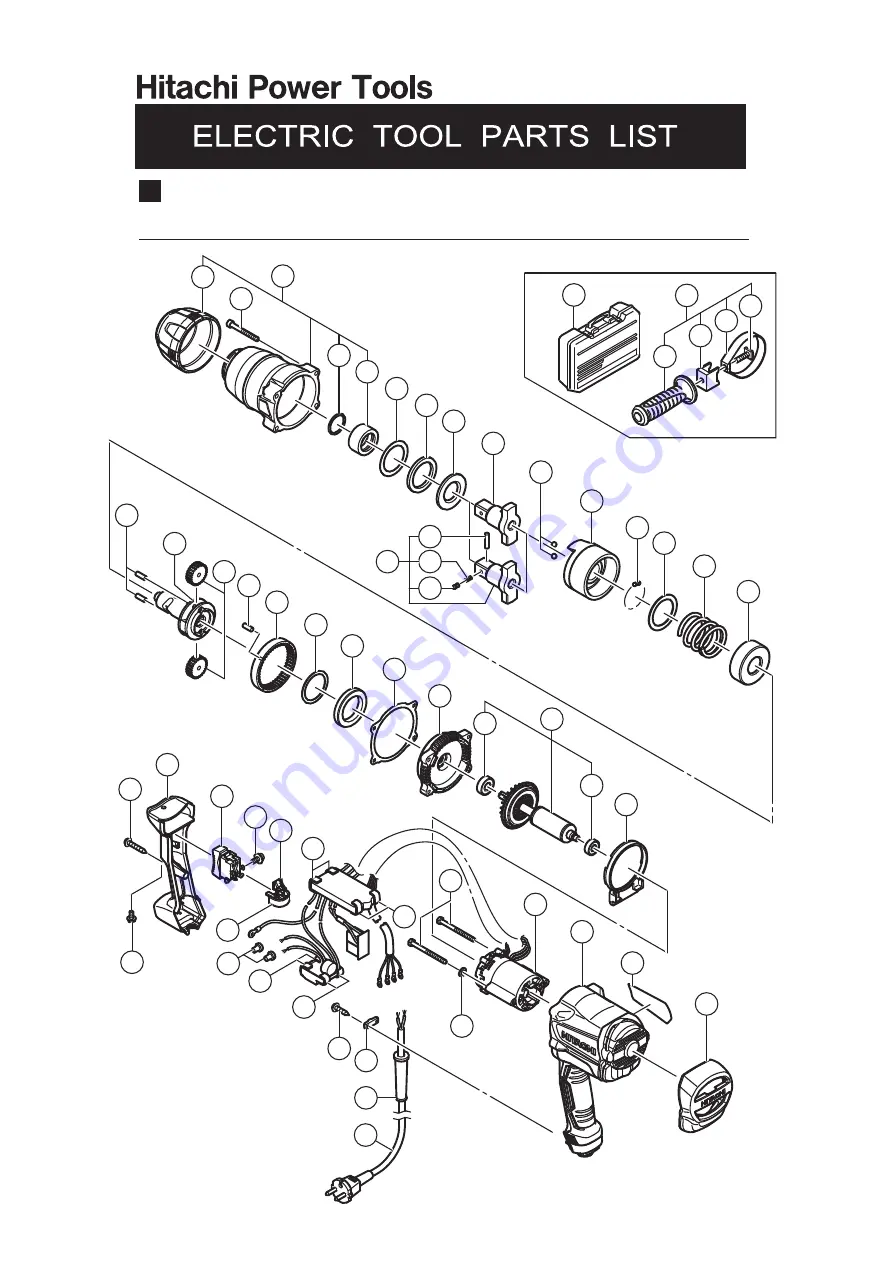
Model WR 22SE

IMPACT WRENCH

LIST NO. E729

2015 · 1 · 20

(E1)

7

8

50

1

2

3

4

5

6

9

10

11

12

13

14

15

16

17

18

9

19

20

21

22

23

24

25

26

27

28

29

30

31

32

33

37

38

39

41

34

35

36

45

46

47

48

49

501

505

502

503

504

506

40

42

43

42

42

43

44

Содержание WR 22SE

Страница 1: ...itachi Impact Wrench Model WR 22SE LIST No xxx 2014 REPAIR GUIDE 1 1 Precautions on disassembly and reassembly 1 STANDARD REPAIR TIME UNIT SCHEDULE 10 CONTENTS Overseas Sales Division LIST No WR 22SE E729 Jan 2015 W ...

Страница 2: ...t M4 44 and four Bolts M5 x 45 3 Supporting Hammer Case D Ass y 1 tap the tip of the Anvil 9 with a wooden hammer to remove Hammer Case D Ass y 1 Remove Packing D 26 from between Hammer Case D Ass y 1 and Inner Cover D 27 2 Removal of the anvil Remove the Anvil 9 from the bearing portion of Hammer Case Ass y D 1 3 Removal of the ring gear Tap the end surface of Hammer Case Ass y D 1 with a wooden ...

Страница 3: ...ls D7 14 10 from the cam grooves of the Spindle 20 and Hammer D 11 Then slowly release the hand press and remove Hammer D 11 from the Spindle 20 to remove the Spring 14 NOTE Be careful not to lose the thirty eight Steel Balls D3 97 12 and the Hammer Washer 13 mounted between Hammer D 11 and the Spring 14 10 11 12 13 14 15 19 20 21 20 11 10 Raised portion of the hammer Top of the spindle cam Steel ...

Страница 4: ...29 together with Inner Cover D 27 from Housing D 34 NOTE Keep the removed Rotor Ass y D 29 away from iron or other metal because Rotor Ass y D 29 has a magnetic force 2 Remove the two Screws D4 x 60 32 Screw D4 x 35 37 and two Screws D4 x 16 46 Then remove the power supply unit 36 27 28 29 30 31 34 38 37 44 46 47 32 33 34 50 ...

Страница 5: ... 4 Fig 6 Removal of the switch 4 Removal of the switch Remove the four Screws M3 5 x 5 40 from the Switch 39 and remove the Switch Adapter 41 Then remove the Switch 39 37 38 39 40 41 34 44 43 ...

Страница 6: ...ws M3 5 x 5 40 from the Switch 39 2 Hold the Switch Adapter 41 and slowly pull it out Internal wire black Internal wire white Internal wire black 39 Sensor PCB ass y 49 48 Filter PCB ass y 45 Noise suppressor PCB ass y Main PCB ass y Internal wire white Internal wire white 43 42 42 42 41 40 Internal wire red ...

Страница 7: ...Use a hand press or similar tool to press the raised portion of Hammer D 11 so as to compress the Spring 14 until it contacts the Spindle 20 and then hold it there 3 Put the two Steel Balls D7 14 10 in the steel ball insertion groove Check that the Steel Balls D7 14 10 are in the cam groove and then release the hand press 4 Mount the Idle Gear Set 2 pcs 21 and the two Gear Shafts 19 on the Spindle...

Страница 8: ... Gear 23 to the impact mechanism and mount it to Inner Cover D 27 NOTE Mount the Ring Gear 23 with its protrusion toward the hammer case 8 Mount Washer F 8 to the Anvil 9 Apply a small amount of grease to the Needle Roller 22 and mount it to the Ring Gear 23 9 Insert Washer D 6 and Damper D 7 into Hammer Case D Ass y 1 and secure it with the four Bolts M5 x 45 3 10 Secure Handle Cover D 38 and Ham...

Страница 9: ...cm Tapping Screw W Flange D4 x 16 46 2 0 0 5 N m 20 5 kgf cm Check the following after reassembly 1 Operate the Switch 39 and check that the switch moves smoothly and the switch operations ON OFF forward and reverse are normal 2 Press the Switch 39 in R direction and slowly release the switch Check that the switch returns to the original position Then press the Switch 39 in L direction and slowly ...

Страница 10: ...s y Switch 39 Main PCB ass y Filter PCB ass y After no load operation for 30 minutes the no load current value should be as follows Voltage 110 V 120 V 220 V 230 V 240 V Current max 3 5 A 3 5 A 1 5 A 1 5 A 1 5 A No load current Connecting diagram ...

Страница 11: ...Armor Tail Bumper D Switch Cord Rotor Ass y D Ball Bearing 6000DD Ball Bearing 608VV Inner Cover D Hammer D Steel Ball D7 14 x 2 Steel Ball D3 97 x 10 Spring Spring Seat Hammer Case D Ass y O ring Anvil Ring Gear Housing D Stator Controller D Set Spindle Idle Gear Set Gear Shaft x 2 STANDARD REPAIR TIME UNIT SCHEDULE ...

Страница 12: ...IMPACT WRENCH LIST NO E729 2015 1 20 E1 7 8 50 1 2 3 4 5 6 9 10 11 12 13 14 15 16 17 18 9 19 20 21 22 23 24 25 26 27 28 29 30 31 32 33 37 38 39 41 34 35 36 45 46 47 48 49 501 505 502 503 504 506 40 42 43 42 42 43 44 ...

Страница 13: ...03 RING GEAR 1 24 337847 WASHER E 1 25 337846 METAL E 1 26 337842 PACKING D 1 27 337845 INNER COVER D 1 28 6000DD BALL BEARING 6000DDCMPS2L 1 29 360990 ROTOR ASS Y D 1 INCLUD 28 30 30 333945 BALL BEARING 608VV 1 31 337844 FAN GUIDE D 1 32 960108 HEX HD TAPPING SCREW D4 X 60 2 33 340897C STATOR CONTROLLER D SET 110V 1 33 340897D STATOR CONTROLLER D SET 120V 127V 1 33 340897E STATOR CONTROLLER D SET...

Страница 14: ...RD 1 CORD ARMOR D8 8 FOR INA IND 49 500439Z CORD 1 CORD ARMOR D8 8 FOR AUS NZL 49 500240Z CORD 1 CORD ARMOR D8 8 FOR USA CAN 49 500450Z CORD 1 CORD ARMOR D8 8 FOR GBR 230V 49 500461Z CORD 1 CORD ARMOR D8 8 FOR GBR 110V 49 500248Z CORD 1 CORD ARMOR D8 8 FOR SUI 49 500496Z CORD 1 CORD ARMOR D8 8 FOR CHN 49 500475Z CORD 1 CORD ARMOR D8 8 FOR KOR 49 500487Z CORD 1 CORD ARMOR D8 8 FOR BRA 50 323210 BOL...

Страница 15: ...INCLUD 602 603 612 874523 HEX SOCKET ASS Y 32MM X 55L 1 INCLUD 602 603 613 874533 HEX SOCKET ASS Y 35MM X 55L 1 INCLUD 602 603 614 874534 HEX SOCKET ASS Y 36MM X 55L 1 INCLUD 602 603 615 955028 HEX SOCKET ASS Y LONG 17MM X 60L 1 INCLUD 602 603 616 955029 HEX SOCKET ASS Y LONG 19MM X 60L 1 INCLUD 602 603 617 955030 HEX SOCKET ASS Y LONG 21MM X 60L 1 INCLUD 602 603 618 955031 HEX SOCKET ASS Y LONG 2...

Отзывы: