background image

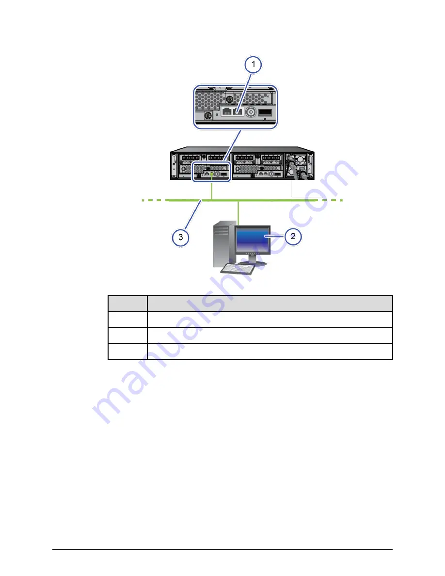
Item

Description

1

Management port on the rear of controller 1

2

Management console

3

Management network

2. Connect the other end of the cable to a management (non-production) network.
3. Connect the management console to the same management network.

Step 5: Power on the storage system

Procedure

1. Power on the PDUs.
2. Confirm that the top (POWER) LED on the lower left front side of the controller is lit

amber, as shown in the following figure. If the storage system has a drive tray,

confirm that the POWER LED on the lower left front side of the drive tray is lit green.

Step 5: Power on the storage system

Installing your storage system

Storage system installation (without SVP)

13

Содержание VSP F350

Страница 1: ...d G370 88 02 0x Storage System Installation without SVP This guide provides information and instructions for installing and setting up your Hitachi Virtual Storage Platform VSP F350 VSP F370 VSP G350 or VSP G370 storage system MK 97HM85020 00 July 2018 ...

Страница 2: ...otherwise from authorized employees and other individuals and 2 Verifying that your data continues to be held retrieved deleted or otherwise processed in accordance with relevant laws Notice on Export Controls The technical data and technology inherent in this Document may be subject to U S export control laws including the U S Export Administration Act and its associated regulations and may be su...

Страница 3: ...ry installed in a rack loosen the band around the cartons and open all boxes Remove all packing materials envelopes and boxes from the cartons 3 Retain all packing materials and cartons in case you need to transport or ship the storage system in the future 4 Check the items you received against the packing list If any items are missing or damaged discontinue the installation and contact your Hitac...

Страница 4: ...k see the documentation for that rack WARNING Due to the heavy weight of the controller use a mechanical lift or at least three people to lift and mount the controller in the rack Before you begin Make sure you have a 19 inch rack that is secure and cannot fall over Make sure the rack has one or more PDUs installed Verify that all power cables are removed from the AC power receptacles on the rear ...

Страница 5: ...n in the following figure and then use two flathead screws to secure the rails to the front vertical post on the rack Note The flathead screws are M5x10 PZ 2 where PZ 2 refers to the size and type of the Philips head Step 2 Install the storage system into a rack Installing your storage system Storage system installation without SVP 5 ...

Страница 6: ...g rail to fit the length of the rack 5 Use two flathead screws to secure the rails to the rear vertical post on the rack Step 2 Install the storage system into a rack Installing your storage system Storage system installation without SVP 6 ...

Страница 7: ...6 Tighten the four screws on the left mounting rail Step 2 Install the storage system into a rack Installing your storage system Storage system installation without SVP 7 ...

Страница 8: ...ront of the controller touch the vertical face of the rack 9 Find the washers O rings and screws included with the bezel bracket mounting kit part number 043 100885 01 P Then install a washer O ring and screw one per side between the mounting profile of the rack and the mounting ears of the controller The screw engages the threaded hole in the rail Step 2 Install the storage system into a rack Ins...

Страница 9: ...Screw 2 O ring 3 Washer The rack installation for your controller should resemble the following figure Step 2 Install the storage system into a rack Installing your storage system Storage system installation without SVP 9 ...

Страница 10: ...erent branch circuits This arrangement enables the storage system to continue operating if AC power is lost to one power supply Note Multiple outlets in a PDU or power strip do not constitute an independent electrical source Procedure 1 Confirm that all power sources are off 2 Connect an AC power cable to the power receptacle on the rear of each controller 3 Route the power cables from each contro...

Страница 11: ...nch circuits Note To prevent the storage system from being turned off by accident make sure the external power sources are not controlled by a wall switch Step 3 Connect the storage system to power Installing your storage system Storage system installation without SVP 11 ...

Страница 12: ...nt console for setting up the storage system for the first time and thereafter to manage the storage system The management console must have a supported web browser Internet Explore version 11 or later Chrome or Firefox Procedure 1 Connect one end of the Ethernet cable to the management port on the rear of either controller The following figure shows the connection to the management port on contro...

Страница 13: ...nt network Step 5 Power on the storage system Procedure 1 Power on the PDUs 2 Confirm that the top POWER LED on the lower left front side of the controller is lit amber as shown in the following figure If the storage system has a drive tray confirm that the POWER LED on the lower left front side of the drive tray is lit green Step 5 Power on the storage system Installing your storage system Storag...

Страница 14: ...ollows a Line up the two tabs on the left side of the controller or drive tray with the two slots on the left side of the bezel b Connect the bezel by sliding it on and swinging the bezel closed c Use the key to secure the bezel to the front of the unit Step 5 Power on the storage system Installing your storage system Storage system installation without SVP 14 ...

Страница 15: ...ezel removed 3 READY LED on controller front bezel removed 4 POWER LED on controller front bezel removed 5 READY LED on controller front bezel attached 6 POWER LED on controller front bezel attached 5 Wait for the green READY LED on the front of the controller to go on approximately 16 25 minutes Note If the READY LED does not go on after 30 minutes contact customer support Step 5 Power on the sto...

Страница 16: ...on production network 2 Configure the management console to use an IP address of 192 168 0 18 and a subnet mask of 255 255 255 0 Next steps Change the storage system s default password Changing the default password To prevent unauthorized access to your storage system change the default password Procedure 1 On your management console PC or laptop open a web browser and enter the following IP addre...

Страница 17: ...ess and subnet mask are correct and pop ups are allowed but the login window does not appear contact customer support 3 In the top right corner click the gear icon and then select User Administration 4 Click Support Personnel Group 5 On the Users tab select the maintenance user check box if it is not already selected and then click Edit Changing the default password Installing your storage system ...

Страница 18: ...ant This password is required for storage system maintenance and for running the Initial Setup wizard Record the new password for the maintenance user and keep it in a safe location 7 Click Finish and then click OK Apply and Close Next steps Run the Initial Setup wizard Changing the default password Installing your storage system Storage system installation without SVP 18 ...

Страница 19: ... Embedded and then open the maintenance utility by clicking the gear icon at the top right corner and selecting User Administration Procedure 1 In the maintenance utility navigation tree under Menu click Initial Setup Wizard Tip Initial Setup Wizard is near the bottom of the navigation tree If you do not see this selection scroll down the tree 2 At the bottom click Skip this step two times to bypa...

Страница 20: ...stem will be connected IPv4 only IPv6 Address IPv6 address of the production network to which the storage system will be connected IPv6 only Subnet Mask IP address mask that identifies the range of IP addresses in the subnet to which the storage system will be connected Subnet Prefix Length Subnet prefix length of the network to which the storage system will be connected IPv6 only Running the Init...

Страница 21: ...s the storage system at the highest speed and appropriate duplex setting supported by itself and the connected device Option DNS Domain Name IP address of the DNS server that will perform address resolution DNS Search Order Search domain names Use the Up and Down buttons to order the domain names Maintenance Port Do not change these values Internal Network Do not change this value 4 Click Apply an...

Страница 22: ...roduction network 6 Connect one end of another Ethernet cable to the management port on the rear of the other controller Connect the other end of the cable to your production network Running the Initial Setup wizard Installing your storage system Storage system installation without SVP 22 ...

Страница 23: ...e new IP address you specified in the Initial Setup wizard and the new password you specified for the maintenance user 9 In the top right corner click the gear icon and then select User Administration 10 In the maintenance utility navigation tree under Menu click Initial Setup Wizard 11 Enter the system information and then click Apply and Next Running the Initial Setup wizard Installing your stor...

Страница 24: ...utility so use a name that is meaningful Contact Name of the contact person associated with the storage system Location Location of the storage system 12 Enter the date and time settings and then click Apply and Next Running the Initial Setup wizard Installing your storage system Storage system installation without SVP 24 ...

Страница 25: ...lock for Daylight Saving Time If the time zone in which the storage system is located follows Daylight Saving Time check this box to have the storage system automatically adjust its time twice a year Running the Initial Setup wizard Installing your storage system Storage system installation without SVP 25 ...

Страница 26: ... No Do not synchronize system time with an NTP server In Date Time enter the date and time that the storage system will use Synchronizing Time To synchronize the storage system time with the NTP server at a specific time enter the time when the two will be synchronized 13 Confirm or change the network settings that you entered earlier in this procedure and then click Apply 14 When prompted that in...

Страница 27: ...d for configuring email notifications we recommend that you set up email notifications using Hi Track Remote Monitoring system 2 To configure the storage system to send notifications in syslog format complete the settings in the Syslog tab Then open a firewall port on your network for transferring syslogs 3 To configure the storage system to send notifications as SNMP traps complete the settings i...

Страница 28: ... hosts and host attachment hardware see the Hitachi Vantara Interoperability Reports For information about preparing your hosts HBAs CNAs NICs and iSCSI initiators for use with the storage system see the documentation for the product The following figure shows the port assignments on the storage system Cabling Fibre Channel ports Each controller supports 8 16 32 Gbps Fibre Channel connectivity to ...

Страница 29: ...s 10 gigabit Ethernet copper RJ 45 or optical fiber iSCSI connectivity to your data network Important For important information and instructions about connecting to hosts refer to the Open Systems Host Attachment Guide Before you begin Make sure the storage system is connected to your production network Procedure 1 Using the appropriate cable connect the iSCSI data ports on each storage system con...

Страница 30: ...now Otherwise you will not be able to download and install Hi Track Remote Monitoring system and you will encounter delays in getting your storage system running and supported Before you begin If you do not yet have a Support Connect account register on Support Connect For details click here Procedure 1 Locate the product serial number labeled MFG NO on the rear of the controller You will need thi...

Страница 31: ...m and notifies the Hitachi Vantara Support Center when assistance is required Hi Track runs on Windows Linux and Solaris operating systems Before you begin If you do not have a Support Connect account register for Support Connect You will need your product serial number and an e mail domain that is recognized as a Hitachi Vantara customer Log in to Support Connect to obtain the Site ID for the loc...

Страница 32: ...r Hitachi Command Suite Typical configuration activities include the following Set up spare drives Create pools and volumes Configure Fibre Channel and iSCSI ports Create a message that appears at login Create user accounts and then back up the accounts For more information see the software user documentation Read the release notes Your storage system undergoes constant development and improvement...

Страница 33: ...resources provide additional information about the storage system Support Connect home page Product interoperability Hitachi Vantara Community Support Installing your storage system Storage system installation without SVP 33 ...

Страница 34: ...ara Corporate Headquarters 2845 Lafayette Street Santa Clara CA 95050 2639 USA HitachiVantara com community HitachiVantara com Contact Information USA 1 800 446 0744 Global 1 858 5474526 HitachiVantara com contact ...

Отзывы: