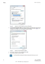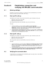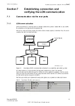
Setting up the PC to access the IED via a network
The same method is used as for connecting to the front port.
The PC and IED must belong to the same subnetwork for this set-up to work.
4.6
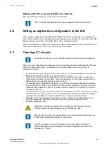
Writing an application configuration to the IED
M11734-2 v7
When writing a configuration to the IED with PCM600, the IED is automatically set in configuration
mode. When the IED is set in configuration mode, all functions are blocked. The red LED on the IED
flashes, and the green LED is lit while the IED is in the configuration mode.
When the configuration is written and completed, the IED is automatically set into normal mode. For
further instructions please refer to the users manuals for PCM600.
4.7
Checking CT circuits
M12182-2 v15
Check that the wiring is in strict accordance with the supplied connection diagram.
The CTs must be connected in accordance with the circuit diagram provided with the IED, both with
regards to phases and polarity. The following tests shall be performed on every primary CT
connected to the IED:
•
Primary injection test to verify the current ratio of the CT, the correct wiring up to the protection
IED and correct phase sequence connection (that is L1, L2, L3.)
•
Polarity check to prove that the predicted direction of secondary current flow is correct for a
given direction of primary current flow. This is an essential test for the proper operation of the
differential function and directional protection functions.
•
CT secondary loop resistance measurement to confirm that the current transformer secondary
loop DC resistance is within the specification for the connected protection functions. When the
measured loop resistance is near the calculated value for maximum DC resistance, perform a
complete burden test.
•
CT excitation test in order to confirm that the current transformer is of the correct accuracy rating
and that there are no shorted turns in the current transformer windings. Manufacturer's design
curves must be available for the current transformer to compare the actual results.
•
Earthing check of the individual CT secondary circuits to verify that each three-phase set of
main CTs is properly connected to the station earth and only at one electrical point.
•
Insulation resistance check.
While the CT primary is energized, the secondary circuit shall never be open
circuited because extremely dangerous high voltages may arise.
Both the primary and the secondary sides must be disconnected from the line and
the IED when plotting the excitation characteristics.
If the CT secondary circuit earth connection is removed without the current
transformer primary being de-energized, dangerous voltages may result in the
secondary CT circuits.
1MRK 511 403-UEN Rev. L
Section 4
Starting up
Bay control REC670
45
Commissioning manual
© 2017 - 2022 Hitachi Energy. All rights reserved
Содержание REC670
Страница 1: ...Relion 670 SERIES Bay control REC670 Version 2 2 IEC Commissioning manual ...
Страница 2: ......
Страница 28: ...22 ...
Страница 54: ...48 ...
Страница 60: ...54 ...
Страница 66: ...60 ...
Страница 90: ...84 ...
Страница 212: ...206 ...
Страница 218: ...212 ...
Страница 232: ...226 ...
Страница 240: ...234 ...
Страница 241: ...235 ...

