11.4.11
Overcurrent protection with binary release BRPTOC
GUID-EB5AEFC4-6F51-4E1E-8055-4FEC53CA81FD v3
Prepare the IED for verification of settings outlined in Section
"Preparing the IED to verify settings"
Logical signals for BRPTOC protection are available on the local HMI under
Main menu /
Settings /IED Settings /Current protection /OvercurrBinRel (50, 3I>) /BRPTOC (50, 3I>):x
.
The Signal Monitoring in PCM600 shows the same signals that are available on the local HMI.
11.4.11.1
Function revision history
GUID-23898A65-D896-479E-9122-E8D9D6CC4FEB v1
Document
revision
Product
revision
History
A
2.2.1
-
B
2.2.1
-
C
2.2.2
-
D
2.2.3
-
E
2.2.3
-
F
2.2.4
-
G
2.2.4
-
H
2.2.4
-
J
2.2.4
-
K
2.2.5
New function release
11.4.11.2
Measuring the operate limit of set values
GUID-4FF9AAC6-04B7-4A26-9093-C199C0C50540 v4
1.
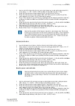
Check that the input logical signals BLOCK and BLKTR and the output logical signal TRIP are
all logical zero.
2.
If required, activate the input RELEASE on the BRPTOC function block.
3.
Set
MeasType
to DFT for overcurrent operation.
4.
For a short while inject a current (fault current) in phase L1 to about 110% of the set operating
current
I>
, and switch the current off.
Observe to not exceed the maximum permitted overloading of the current circuits in the IED.
5.
Switch the fault current on and observe that STL1 and START appears. Also, measure the
operating time of BRPTOC.
Use the TRIP signal from the configured binary output to stop the timer. Repeat step 4 and step
5 by changing
MeasType
to Peak and Peak-to-peak and observe the operate time of BRPTOC.
6.
Activate the input BLOCK on the BRPTOC function block.
7.
Switch on the fault current (110% of the setting) and observe.
No STL1, START, and TRIP signal should appear.
8.
Switch off the fault current.
9.
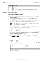
For a short while inject a current (fault current) in same phase to about 90% of the set
operating current, and switch the current off.
10.
Switch the fault current on and observe.
No STL1, START, and TRIP signal should appear.
11.
Switch off the fault current.
12.
If required, reset the RELEASE binary input.
13.
Switch the fault current on.
No STL1, START, and TRIP signal should appear.
14.
Switch the fault current off.
15.
Repeat the above steps by injecting fault current in phase L2 and L3.
1MRK 511 403-UEN Rev. L
Section 11
Testing functionality by secondary injection
Bay control REC670
105
Commissioning manual
© 2017 - 2022 Hitachi Energy. All rights reserved
Содержание REC670
Страница 1: ...Relion 670 SERIES Bay control REC670 Version 2 2 IEC Commissioning manual ...
Страница 2: ......
Страница 28: ...22 ...
Страница 54: ...48 ...
Страница 60: ...54 ...
Страница 66: ...60 ...
Страница 90: ...84 ...
Страница 212: ...206 ...
Страница 218: ...212 ...
Страница 232: ...226 ...
Страница 240: ...234 ...
Страница 241: ...235 ...


