

4. Preparation of Pipe
●
Use a pipe cutter to cut the copper pipe.
●
Before flaring, please put on the flare nut.
Outer
Diameter (Ø)
6.35 (1/4”)
9.52 (3/8”)
12.7 (1/2”)
Imperial flaring tool
0
~
0.5mm
0
~
0.5mm
0
~
0.5mm
Rigid flaring tool
A (mm)
●
Please use exclusive
tool
Copper
pipe
Trimming tool
A
Die
Die
Copper pipe
1.0mm
1.0mm
1.0mm
Wrench
Torque
wrench
Flare nut
Outer diameter of pipe (Ø)
Torque N·m (kgf · cm)
Small diameter side
●
Please be careful when bending the copper pipe.
●
Screw in manually while adjusting the center. After that, use of torque wrench to tighten the connection.
Large diameter side
6.35 (1/4”)
13.7-18.6 (140-190)
9.52 (3/8”)
34.3-44.1 (350-450)
12.7 (1/2”)
44.1-53.9 (450-550)
Small diameter side
Large diameter side
6.35 (1/4”)
19.6-24.5 (200-250)
9.52 (3/8”)
19.6-24.5 (200-250)
12.7 (1/2”)
29.4-34.3 (300-350)
Valve head
cap
12.3-15.7 (125-160)
Valve core cap
Connecting cord should
have arranged with piping
using tape previously.
Pipe connection port for Indoor unit No. 1
Pipe connection port for Indoor unit No. 2
Indoor unit No. 1
Indoor unit No. 2
CAUTION
!
●
In case of removing flare nut of a indoor unit, first remove a nut of small diameter side, or seal cap of large
diameter side will fly out. Free from water into the piping when working.
●
During connection, keep away from water.
●
Be sure to tighten the flare nut to the specified torque using a torque wrench. If the flare nut is tightened
excessively, it may crack as time elapses, causing refrigerant leakage.
●
Install the unit in a stable place to minimize vibration or noise.
●
After arranging the cords and pipes, secure them in place.
ONE UNIT
TWO UNITS
POSSIBLE COMBINATIONS
TO OPERATE
AMPERE
(A)
220-240V
CAPACITY RATING
(kW) (RANGE)
POWER
CONSUMPTION
(W)
ONE UNIT : The values indicated are only for one unit operation when two indoor units are connected.
OUTDOOR UNIT
COOLING
AMPERE
(A)
220-240V
CAPACITY RATING
(kW) (RANGE)
POWER
CONSUMPTION
(W)
OUTDOOR UNIT
HEATING
(Reference value)
COOL/HEAT CAPACITY SPEC, FOR INDOOR UNITS COMBINATIONS
Gas leakage inspection
Please use gas leakage detector to check if leakage occurs
at connection of flare nut as shown on the right.
If gas leakage occurs, further tighten the connection to stop
leakage. (Use the detector provided for R410A)
Lo
Hi
Vacuum for more
than 10 min.
Stop valve
Charge hose
Stop
valve
Vacuum pump adapter
Be sure the stop valve
is always fully opened.
Valve cap
Valve cap of valve core
Valve cap
Valve cap
Valve core
Valve cap of
valve core
Stopper
O-Ring
Pipe
Pipe
Seal cap
Flare nut
Spindle
Meter showing pressure
When the meter reaches -101KPa (-76cmHg) during
pumping, fully tighten the shuttle.
Air purging by vacuum pump
Closed
Vacuum pump
R410A Manifold valve
When pumping starts,
slightly loosen the flare
nut to check of air
sucked in. Then tighten
the flare nut.
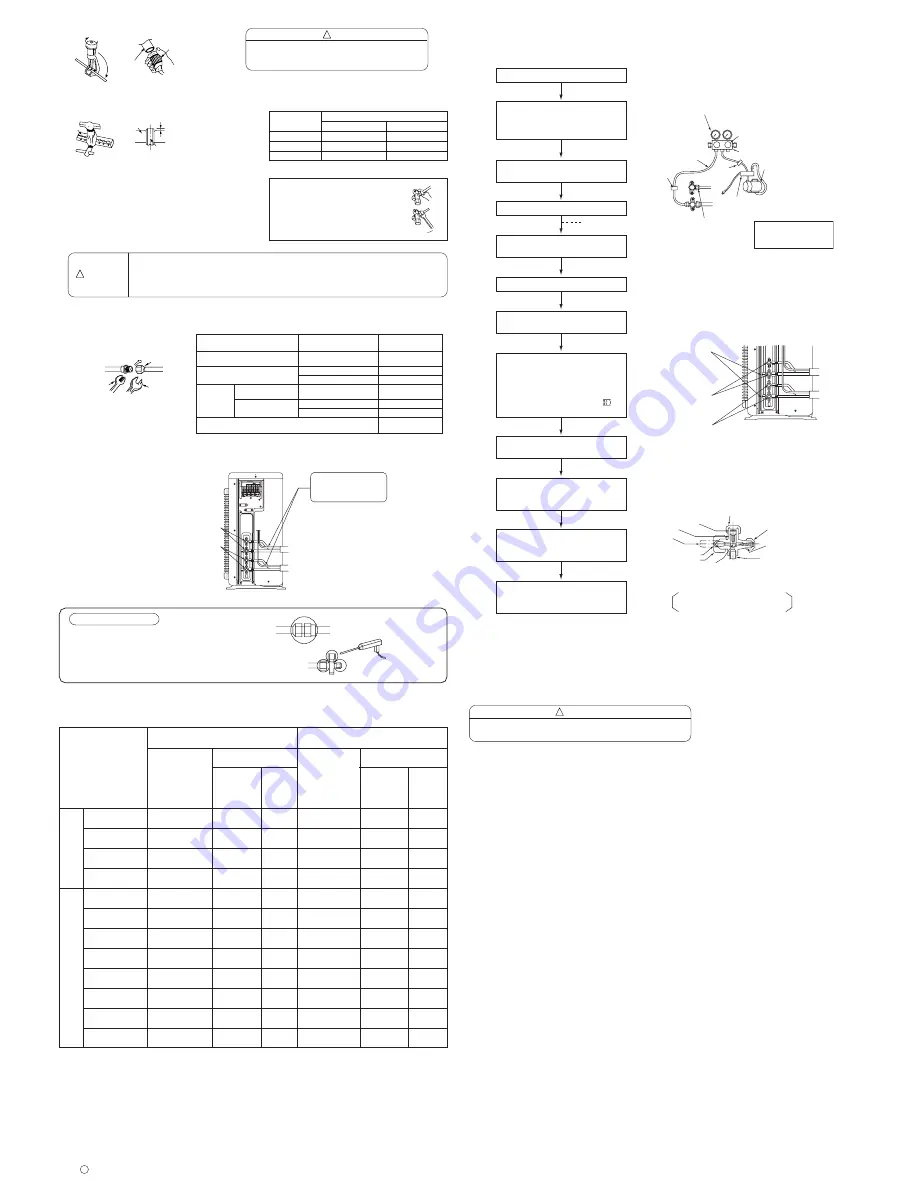
The refrigerant channel is opened so
that the refrigerant will flow from the
outdoor unit into the indoor unit.
Remove the valve cap of valve core.
Run the vacuum pump.
Stop the vacuum pump.
Connect the charge hoses to the
vacuum pump and the charge port of
the valve core large dia. pipe side
service valve, respectively.
Remove the valve cap from the
spindle of the service valve.
Disconnect the charge hose from the
service valve.
Tighten the valve cap of valve core.
[Torque 12.3 - 15.7 N
¥
m (125 - 160
kgf
¥
cm)]
Attach the valve cap to the spindles
of each large and small dia. pipe
side service valves.
Tighten the valve cap of the spindle.
[Torque 19.6 - 24.5 N
¥
m (200 - 250
kgf
¥
cm)]
Turn the spindles of each large and
small dia. pipe side service valves
full counterclockwise until they are
securely tightened. Then retighten
them more than 10 degrees [using a
hexagon wrench key (4mm )
without fail].
Fully open the LO knob of the
manifold valve.
Close the LO knob of the manifold
valve.
Tighten all the way by hand.
Do not tighten all at once, but tighten it while
fitting the flared surface to the pipe.
CAUTION
!
5. Pipe Connection
5.1 Pipe connection
Connecting the pipe to outdoor unit
(1) Remove the flare nut and seal cap from the service valve.
(2) Apply refrigerator oil to the service valve and the flared portion
of the pipe.
(3) Using a wrench, security tighten.
●
Jagged edge will cause leakage.
●
Point the side to be trimmed downwards during trimming to
prevent copper chips from entering the pipe.
7. Operation test
●
Please ensure that the air conditioner is in normal operating condition during the operation test.
●
Explain to your customer the proper operation procedures as described in the user’s manual.
●
If the indoor unit does not operate, check to see that the connections are correct.
CAUTION
●
Trial run should be conducted on one unit at a time to check for incorrect
wiring of connecting cord.
!
6. Removal Of Air From The Pipe And Gas Leakage Inspection
6.1 Air purging by using vacuum pump
Fig. 6-1
Fig. 6-2
Fig. 6-3
<
I920: A
>
1.8
2.5
3.5
5.0
1.8 + 1.8
1.8 + 2.5
1.8 + 3.5
1.8 + 5.0
2.5 + 2.5
2.5 + 3.5
3.5 + 3.5
2.5 + 5.0
1.80
(1.00 – 2.50)
2.50
(1.00 – 2.80)
3.50
(1.00 – 3.90)
5.00
(1.00 – 5.60)
1.80 + 1.80
(1.50 – 4.00)
1.80 + 2.40
(1.50 – 4.60)
1.70 + 3.30
(1.50 – 5.60)
1.40 + 4.00
(1.50 – 5.90)
2.50 + 2.50
(1.50 – 5.60)
2.17 + 3.03
(1.50 – 5.70)
2.70 + 2.70
(1.50 – 5.90)
1.80 + 3.60
(1.50 – 5.90)
2.6 – 2.4
3.6 - 3.3
5.3 – 4.9
8.2 – 7.5
5.5 – 5.0
6.0 – 5.5
7.6 – 6.9
8.2 – 7.6
7.6 – 6.9
7.9 – 7.3
8.2 – 7.6
8.2 – 7.6
3.4 – 3.2
5.3 – 4.8
7.1 – 6.5
11.0 – 10.1
6.7 – 6.1
8.4 – 7.7
9.2 – 8.4
9.4 – 8.6
9.3 – 8.5
9.5 – 8.7
9.7 – 8.9
9.7 – 8.9
560
(200 – 750)
780
(200 – 980)
1160
(200 – 1280)
1780
(200 – 1960)
1190
(200 – 1300)
1310
(200 – 1450)
1650
(200 – 1820)
1795
(200 – 1980)
1650
(200 – 1820)
1730
(200 – 1900)
1795
(200 – 1980)
1795
(200 – 1980)
2.50
(1.10 – 3.20)
3.90
(1.10 – 4.70)
4.80
(1.10 – 5.80)
6.50
(1.10 – 7.20)
2.50 + 2.50
(1.50 – 5.20)
2.40 + 3.80
(1.50 – 6.30)
2.30 + 4.50
(1.50 – 7.20)
2.00 + 5.00
(1.50 – 7.20)
3.40 + 3.40
(1.50 – 7.20)
3.15 + 3.85
(1.50 – 7.20)
3.60 + 3.60
(1.50 – 7.20)
2.70 + 4.50
(1.50 – 7.20)
750
(200 – 1050)
1145
(200 – 1380)
1550
(200 – 1870)
2400
(200 – 2660)
1460
(200 – 1550)
1820
(200 – 1920)
1995
(200 – 2100)
2050
(200 – 2100)
2015
(200 – 2110)
2070
(200 – 2110)
2110
(200 – 2110)
2110
(200 – 2110)