background image

51

ENGLISH

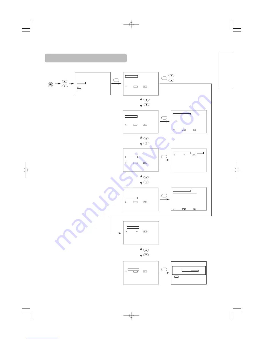
SETUP MENU

  Picture
  Audio
  Timer
  Function
  Setup
  Language
     Select
   OK  Set

Setup
  Auto Tuning
  Manual Tuning
  Fine Tuning
  Sort
  Auto Off 


Off 

     Select            Set              Return

OK

OK

MENU

Setup
  Auto Tuning
     Mode 


Position

        Search 
     Select            Set              Return

OK

Setup
  Auto Tuning
     Mode 


Position

        Search 
     Select            Set              Return

Setup
  Auto Tuning


Scanning Channel Number: 33


             Cancel

OK

Cancel

Setup
  Auto Tuning
  Manual Tuning
  Fine Tuning
  Sort
  Auto Off 


Off 

     Select            Set              Return

OK

Setup
  Auto Tuning
  Manual Tuning
  Fine Tuning
  Sort
  Auto Off 


Off 

     Select            Set              Return

OK

Setup
  Auto Tuning
  Manual Tuning
  Fine Tuning
  Sort
  Auto Off 


Off 

     Select            Set              Return

OK

Setup
  Manual Tuning
    Position 

  99

    Frequency 

250MHz

    Name 

ABCDE 

    Sound System 

BG

    Color System 

Auto


Skip Off 


    NR  

Off

     Select            Return          Exit

Setup  


            Prog.No.199

  Fine Tuning 

+56  

     Select            Adjust           Return

Setup
  Sort
   Position  Name 

MHz

    100 

ABCDE    62MHz

    101 

BBC1 

  83MHz

    102 

----- 

  97MHz 

    103 

BBC 

106MHz

    104 

FGHIJ 

175MHz


105 XYZAB 

189MHz 


    106 

----- 

199MHz

    107 

----- 

225MHz

     Select            Return          Exit

OK

OK

OK

OK

OK

[During TV mode]

01  QR58553-英語-初校  03.10.15  10:47 AM  ページ51

Downloaded from 

www.Manualslib.com


manuals search engine


Содержание Plasma Display Monitor

Страница 1: ...ct is marketed assuming that it is installed by qualifed personnel with enough skill and competence Always have an installation specialist or your dealer install and set up the product HITACHI cannot assume liabilities for damage caused by mistake in installation or mounting misuse modification or a natural disaster Note for Dealers After installation be sure to deliver this manual to the customer...

Страница 2: ...024 V pixels creates a high definition large screen aspect ratio 16 9 and low profile flat display Free from electromagnetic interferences from geomagnetic sources and ambient power lines the panel produces high quality display images free from color misconvergence and display distortion High Performance Digital Processor A wide range of personal computer signals can be handled from 640 x 400 640 ...

Страница 3: ... this manual you are requested to notify your dealer or us should you have any comments views or questions about our product Fully understand the prerequisites to using the product such as hardware and software specifications and constraints in using the product We are not held liable for damages caused by improper handling of the product Reproduction of this manual in whole or in part without our...

Страница 4: ...k Use special caution in households where children are present If liquids or foreign objects should enter the projector immediately turn off the power switch disconnect the power plug from the power outlet and contact your dealer Do not place the monitor in a bathroom Do not expose the monitor to rain or moisture Do not place flower vases pots cups cosmetics liquids such as water etc on or around ...

Страница 5: ...his could result in the inadvertent placing of heavy objects on the concealed power cord or cables Do not pull the power cord and cables When connecting and disconnecting the power cord or cables do it with your hand holding the plug or connector Do not place the cord near the heater Do not touch the power plug just after disconnecting it from the power outlet to prevent electric shock Do not touc...

Страница 6: ...bjects Clean the screen with a soft cloth moistened with warm water and dry with a soft cloth If it is not enough then use a cloth with mild detergent Do not use harsh or abrasive cleaners How to clean the cabinet of the monitor Use a soft cloth to clean the cabinet and control panel of the monitor When excessively soiled dilute a neutral detergent in water wet and wring out the soft cloth and aft...

Страница 7: ...trong rays such as direct sun rays or room lighting onto the remote control sensors could invalidate the remote control Avoid radio interference Any interfering radiation could cause distorted images or noises Avoid radio generator such as a mobile telephone transceiver etc around the monitor Set the sound volume at a suitable level It is better to keep the volume level low and close the windows a...

Страница 8: ... 15 Adjustment buttons are located on the bottom The back cover is provided with indications to distinguish the adjustment buttons SUB POWER button 13 Control panel VOLUME UP DOWN buttons ADJUST buttons 14 Main power switch 13 13 The main power switch is located at the back on the lower surface 42 32 Indicating lamp External device connection terminals Rear RGB input terminals 11 External speaker ...

Страница 9: ...e new and old batteries together The batteries could explode or leak resulting in fires physical injury or stains When loading batteries observe their correct polarities as marked on the product If loaded in the wrong direction the batteries could explode or leak resulting in fires physical injury or stains CAUTION ATTENTION Do not drop or impact the remote control Do not splash the remote control...

Страница 10: ... prevent an internal temperature increase maintain a space of 10cm 4 inches For a desktop set up or more between the sides and other objects such as walls etc so that the ventilation holes are not blocked CAUTION Have this unit mounted in a stable place Take measures to prevent it from tumbling down to avoid possible physical injury CAUTION 10cm 4 inches or more Cord or chain Clamp Two places Wood...

Страница 11: ...GB 1 or RGB 2 on the rear panel of this device to the display signal output terminal of the personal computer Use a cable that fits the input terminal of this device and the output terminal of the personal computer Depending on the type of personal computer being connected the use of an optional conversion adapter or the adapter provided with the personal computer may be necessary in some cases Fo...

Страница 12: ...LLATION INSTRUCTIONS continued Power Cord Connection Use only the power cord provided Do not use a power supply voltage other than that indicated AC100 240V 50 60Hz as this may cause fire or electric shock CAUTION Mounting the Speaker Unit option Refer to the instruction manual concerning mounting of the optional speaker unit 01 QR58553 英語 初校 03 10 15 10 47 AM ページ12 Downloaded from www Manualslib ...

Страница 13: ... of the front of the frame is ON Lights orange Off Power Save When the main power switch is ON and the ON button on the remote control or the SUB POWER button on the underside of the front of the frame is ON However the state in POWER SAVE mode When the indicating lamp lights in orange or the message No Sync Signal Power Save or Invalid Scan Freq appears on the screen there is something unusual ab...

Страница 14: ...ns of the remote control Input can be switched in the sequence of RGB1 RGB2 by pressing the INPUT SELECT button of the monitor When a button is pressed the volume adjustment status guide will be displayed The volume will increase when the VOL or button is pressed while the guide is being displayed The volume will decrease when the VOL or button is pressed while the guide is being displayed Volume ...

Страница 15: ...rtical frequency The input signal status can be displayed on the screen by pressing the RECALL button of the remote control or the monitor The display will go out in approximately 6 seconds Off timer On timer RGB RECALL button Display area selection diagram RGB input Resolution Full display Circular display Display Full Normal Real Zoom1 Zoom2 Zoom3 640 X 480 VGA 800 X 600 SVGA 1024 X 768 XGA 1280...

Страница 16: ...ors Remote control ID No 2 initially ID no 1 can be set by pressing the ID SET button for 2 sec or more while holding down the ID button The number will be incremented 2 6 7 1 2 when this button pressed continuously The ID remote control is operated by pressing the various buttons while holding down the ID button Operation is possible only when the remote control and monitor ID nos are the same Th...

Страница 17: ...ture depending on the user s preference These settings are independently stored in each of the 4 Color Temperature modes Green Brighter scene is decreased in greenish color Brighter scene is increased in greenish color Blue Brighter scene is decreased in bluish color Brighter scene is increased in bluish color Cut Off Red Dark scene is decreased in reddish color Dark scene is increased in reddish ...

Страница 18: ...y adjust volume so each channel and input has the same average volume level Reset off the function waiting to reset The original factory settings for the items of this Menu page can be restored by pressing the OK button Picture Audio Timer Function Setup Language Select OK Set Audio Audio Mode Movie Treble 10 Bass 10 Balance 0 L R SRS TruBass Middle Matrix Surround Off Perfect Volume Off Reset Res...

Страница 19: ...ing to reset The original factory settings for the items of this Menu page can be restored by pressing the OK button Panel Life Normal Extend 1 Extend 2 This function is to suppress the contrast of the screen regardless of the Contrast setting in the Picture Menu By this control power consumption can be reduced or degradation of a panel can be mitigated The order of power consumption is Extend 2 E...

Страница 20: ... for RGB2 Input Level 0 7V 1 0V Normally set to 0 7 V If white is found to spread across the screen set to 1 0 V This is effective only for RGB2 Frequency Display Off On Set this to Off if the frequency information of the Input Signal Screen Display is not required WVGA Type Off On This is only available for W VGA signal When it is set to On the display area mode can be selected Full or Real Verti...

Страница 21: ... Color Temp Adjust R Amplitude For every Color Temperature 1 setting is registered G Amplitude B Amplitude R Cut Off G Cut Off B Cut Off Audio Audio Mode 1 setting is registered Treble For every Audio Mode 1 setting is registered Bass Balance 1 setting is registered SRS TruBass For every Audio Mode 1 setting is registered Matrix Surround Perfect Volume Menu Display Registration condition Function ...

Страница 22: ...gnal Changes in the signal status are displayed on the screen as they arise OTHER FEATURES continued RGB2 RGB H 48 4kHz V 60 1 Hz Min OFF RGB Invalid Scan Freq Power Save Mode When the RGB1 RGB2 input is selected When this unit is connected to a VESA DPMS computer the Power Save Off mode can be set to be activated automatically when the computer is not being used to reduce power consumption by thi...

Страница 23: ... more the brighter the characters and figures are displayed When images of figures with different levels of brightness as shown in Fig B are continuously displayed for a long period of time it becomes easier for image marks at locations when the brighter figures are displayed to be noticeable The image retention images in this document are exaggerated for the purpose of explanation The actual mann...

Страница 24: ...eived normally Check to see if the input signal matches the monitor specifications Check the way the signal cable is connected The power indicating lamp is normally lit but no picture Check the contrast and brightness settings adjust them for higher contrast and brightness Check the way the signal cable is connected The display image appears flowing slantwise Text displayed across the screen appea...

Страница 25: ...not a malfunction Coarse horizontal stripes appear in FULL display Adjusting the Clock Phase will reduce the horizontal stripes RGB input Flickering in the form of horizontal lines oscillating up and down PC INPUT MODE only If the direct frequency from the computer is below 85Hz try a higher frequency upper limit 85Hz There may be a slight attenuation of the current image Try turning the Vertical ...

Страница 26: ...nd search for clear characters over the entire screen 7 Perform adjustment for symptom 2 below when the characters are blurred on the entire screen The display image may be momentarily disturbed during clock adjustment but this is not a failure Symptom 2 Text displayed across the screen appears blurred in its entirety figure 2 A fine pattern flickers when displayed on the screen figure 3 Example A...

Страница 27: ...1030 W x 636 H x 91 D mm Net weight excluding Speakers Stand 24 6kg 34 9kg Ambient conditions Temperature Operating 5 C to 35 C Storage 0 C to 40 C Relative humidity Operating 20 to 80 Storage 20 to 90 non condensing Power supply AC100 240V 50 60Hz Power consumption at standby 255W 3W 365W 3W Audio output 12W 12W 6Ω RGB input Input signals Input terminals RGB1 DVI input terminal DVI D RGB1 audio i...

Страница 28: ...nput Recommended Signal List No Signal mode Horizontal frequency kHz Dot clock frequency MHz Remarks Signal Name Resolution Vertical frequency Hz 1 VGA 640 X 400 70 08 31 47 25 18 2 640 X 480 59 94 31 47 25 18 3 W VGA 864 X 480 60 00 31 02 33 75 4 864 X 480 59 94 31 47 34 24 WVGA type On 5 VESA 640 X 480 72 81 37 86 31 50 6 640 X 480 75 00 37 50 31 50 7 640 X 480 85 01 43 27 36 00 8 800 X 600 56 2...

Страница 29: ...7 25 18 2 640 X 480 59 94 31 47 25 18 3 W VGA 864 X 480 59 94 31 47 34 24 WVGA type On 4 VESA 640 X 480 72 81 37 86 31 50 5 640 X 480 75 00 37 50 31 50 6 640 X 480 85 01 43 27 36 00 7 800 X 600 56 25 35 16 36 00 8 800 X 600 60 32 37 88 40 00 9 800 X 600 72 19 48 08 50 00 10 800 X 600 75 00 46 88 49 50 11 800 X 600 85 06 53 67 56 25 12 1024 X 768 60 00 48 36 65 00 13 1024 X 768 70 07 56 48 75 00 14...

Страница 30: ...30 SUPPLEMENT 01 QR58553 英語 初校 03 10 15 10 47 AM ページ30 Downloaded from www Manualslib com manuals search engine ...

Страница 31: ...f video equipment with an S video output terminal is used cabling by the S video cable is recommended to provide finer video quality If an S video input terminal and a video input terminal of AV3 connect to the monitor at the same time S video input would govern If the OUTPUT MONITOR terminal is connected to an external monitor with a 75 Ohm terminal it is possible to view the same image as on the...

Страница 32: ...ize selection diagram When you want to Set the display size to Input signal Display screen Remarks Play a 4 3 image in a 16 9 screen faithfully 4 3 Blanking occurs on both sides Play a 4 3 image in a 16 9 screen with the height and width of the middle of the screen enlarged on equal scales and with both sides appearing somewhat enlarged Panoramic Play a 16 9 VISTA size image in the 4 3 image faith...

Страница 33: ...screen in the Panoramic mode parts of the periphery of the image may disappear and or appear distorted in some cases Use the 4 3 mode to view images which were created in 4 3 mode This mode allows 4 3 content to be viewed without picture distortion Press Vertical picture position can be adjusted for Panoramic Zoom and Cinema mode as follows 1 Press SIZE button and SELECT buttons during picture siz...

Страница 34: ...he side on which the speaker icon is located The same video input mode cannot be selected for both screens at the same time Pressing the PinP button again or the RETURN button will cancel the 2 pictures display When the Video input is set to RGB Video this Split mode is not possible Refer to the table for 2 pictures Split mode PinP button RETURN button AV1 AV2 RGB 1 RGB 2 AV3 MUTE VOL VOL AV4 AUTO...

Страница 35: ...ecoding Select Set Return OK Picture Dynamic Color Temp Adjust Color Management Color Decoding Select Set Return OK Picture Color Management On Magenta 60 Red 30 Yellow 0 Green 60 Cyan 30 Blue 0 Reset Reset Select On Off Return OK OK PICTURE MENU OK OK Picture Mode Dynamic Next Prev Select Return YNR Off Next Prev Select Return Picture Dynamic YNR Off CNR Off Film Mode On PAL Comb Filter On LTI Of...

Страница 36: ...ed by pressing the OK button YNR Off Low High Performs picture signal noise reduction Turn up to reduce noise CNR Performs color signal noise reduction Turn up to reduce noise And it will be fixed as Off only when selecting DVI STB mode Film Mode Off On On Automatically detects the movie film material and faithfully reproduces the original film image Off Set to OFF when switching between images do...

Страница 37: ...ightens red only This adjusts R G B level or tint to make the color appear natural for the user s preference These settings are independently stored in each of the 4 Color Temperature modes Green Darkens green only Lightens green only Color Darkens colors Lightens colors Tint Enhances red and weakens green Enhances green and weakens red FUNCTION MENU 1 item is added to the Menu shown in the page P...

Страница 38: ...ignal will be automatically recognized If the input signal contains much noise or has a low level at Auto and the operation is found erratic set this to match the input signal When the component signal is received this would be not available grayed out AV2 Same to AV1 AV3 AV4 Video Input AV1 Auto HDTV SDTV DVD This should correspond to the signal mode of the signal from the equipment that is conne...

Страница 39: ...istered AV1 AV2 AV3 AV4 Video Input AV1 1 setting is registered AV2 AV4 Audio Input AV1 1 setting is registered AV2 AV3 AV4 RGB1 RGB2 The previously recorded items will be lost Selected characters Setup hint Audio Input AV1 Stereo L Mono This should correspond to the audio signal from the equipment that is connected to AV1 audio input terminal If it is monaural audio set this to L Mono AV2 Same to...

Страница 40: ...by 255W 3W 365W 3W Audio output 12W 12W 6Ω RGB input Input signals Input terminals RGB1 DVI input terminal DVI D RGB1 audio input terminal 3 5mm Stereo Mini Jack RGB2 analog RGB input terminal D sub 15 pin RGB2 audio input terminal 3 5mm Stereo Mini Jack Video signals 0 7 V 1 0 Vp p analog RGB Recommended Signal 480i 576i 480p 576p 1080i 50 1080i 60 720p 60 Sync signals H V separate TTL level 2KΩ ...

Страница 41: ...5 6 7 8 9 10 11 12 13 14 15 When different kinds of input signals are simultaneously input to the monitor via a graphics board or the like the monitor will automatically select the signals in the following priority order Even in the case of the recommended signals shown on the following page there may be instances when correct display is not possible In this case use H V separate sync H V composit...

Страница 42: ...tical frequency Hz 1 NTSC4 43 NTSC3 58 525 59 94 15 73 2 PAL SECAM 625 50 00 15 63 With Composite Input AV1 AV4 input and S video Input AV3 input No Signal mode Horizontal frequency kHz Dot clock frequency MHz Remarks Signal Name Resolution Vertical frequency Hz 1 NTSC4 43 3 58 PAL SECAM 525 625 59 94 50 00 15 73 15 63 With R G B Video input AV2 and AV4 input No Signal mode Horizontal frequency kH...

Страница 43: ... in the wrong direction the batteries could explode or leak resulting in fires physical injury or stains CAUTION ATTENTION Do not drop or impact the remote control Do not splash the remote control with water or put it on a wet object to avoid possible failures Before leaving the remote control out of use for an extended period of time remove the batteries from it If the remote control begins to la...

Страница 44: ...TIME Pressing this button can indicate the time by On Screen display when receiving a TV program on the screen including TELETEXT service with the time information AUDIO MODE You may recall the sound mode by pressing this button Each time pressed sound mode is changed in following sequence MATRIX SURROUND Press this button to set Matrix Surround On or Off MULTI PICTURE Press this button to change ...

Страница 45: ...d text page has been received the page number will be displayed at the top left of the screen Press the CANCEL button again to display the TELETEXT screen RED GREEN YELLOW BLUE Each of these buttons selects a link page displayed at the lower part of the screen A FAVORITE page can also be stored in the memory using one of the colors It can then retrieve the page stored by pressing the appropriate c...

Страница 46: ... are good Please use a coaxial cable which is free from interference to connect the antenna Avoid using a parallel flat feeder wire as interference may occur causing reception to be unstable and stripe noise to appear on the screen Avoid using indoor antenna as this may be affected by interference Please use CATV net or outdoor antenna Keep the power cord as far away from the antenna wire as possi...

Страница 47: ...r the remote control VOLUME UP DOWN buttons INPUT SELECT button OK button PROGRAM UP DOWN buttons TV AV1 AV2 AV3 RGB2 RGB1 AV4 Each time the ZOOM button of the remote control is pressed the screen display size will change in sequence and the status will be displayed at the bottom of the screen During TV mode Input Switching Size Switching INPUT SELECT button MUTE button PROGRAM SELECT buttons RGB ...

Страница 48: ...the multi picture mode And then pressing the MULTI PICTURE button again will display the 4 pictures Refer to the table for 4 pictures mode Activating the 12 pictures mode from the TV screen Pressing the MULTI MODE button one time at the 4 pictures mode will display 12 pictures Starting from channel 1 preset channels will automatically display in sequence on the 12 windows This function activates o...

Страница 49: ...SECAM NTSC3 58 NTSC4 43 576i 576p 480i 480p 1080i 50 1080i 60 720p 60 STB Component AV1 AV4 PAL SECAM NTSC3 58 4 43 AV1 AV2 576i 576p 480i 480p 1080i 50 1080i 60 720p 60 RGB1 STB RGB2 Component Available Main Sub Input terminal AV1 AV4 AV1 AV2 RGB1 RGB2 TELE TEXT PAL SECAM NTSC3 58 NTSC4 43 576i 576p 480i 480p 1080i 50 1080i 60 720p 60 STB Component AV1 AV4 PAL SECAM NTSC3 58 4 43 AV1 AV2 576i 576...

Страница 50: ...es TV mode Refer to the table for Freeze function as below FREEZE button Picture Freezing A B 5 1 2 3 4 5 6 7 8 9 10 11 12 Active Split Strobe Split Strobe PAL SECAM NTSC3 58 4 43 576i 480i 576p 480p 1080i 50 1080i 60 720p 60 RGB DVI PC Available FUNCTION MENU Refer to the page It is same to the Picture Menu of Optional Video Unit Function But 2 item is added and 5 items are deleted Selected chara...

Страница 51: ...etup Auto Tuning Manual Tuning Fine Tuning Sort Auto Off Off Select Set Return OK Setup Auto Tuning Manual Tuning Fine Tuning Sort Auto Off Off Select Set Return OK Setup Manual Tuning Position 99 Frequency 250MHz Name ABCDE Sound System BG Color System Auto Skip Off NR Off Select Return Exit Setup Prog No 199 Fine Tuning 56 Select Adjust Return Setup Sort Position Name MHz 100 ABCDE 62MHz 101 BBC...

Страница 52: ...electable letters are 0 9 A Z blank comma and period Sound System Auto M BG DK I Select the sound system through the 5 different settings Color System Auto PAL SECAM NTSC3 58 NTSC4 43 Select the color system through the 5 different settings Skip Off On If this is set to On that position will be skipped while selecting positions by PROGRAM UP DOWN buttons This is automatically set to On for those n...

Страница 53: ...d Green Red Green 8 STEREO sound broadcast When a stereo program is received sound mode display will appear in red and you can press the CH I II button to select between stereo and mono sound Each time the button is pressed or force mono appear cyclically on the screen When receiving NICAM signals NICAM display will appear as below Monaural sound broadcast When a monaural program is received sound...

Страница 54: ...D Player Press Hitachi RCA Pioneer Mitsubishi Panasonic Onkyo Toshiba Zenith Philips Orion JVC Shinco Samsung Skyworth Sony Bubuko RECALL 1 RECALL 2 RECALL 3 RECALL 4 RECALL 5 RECALL 6 RECALL 7 RECALL 8 RECALL 9 RECALL 0 RECALL INDEX RECALL MODE RECALL SUB PAGE RECALL CANCEL RECALL REVEAL RECALL TV TEXT D N A B i MENU OK FREEZE ZOOM AV1 RGB1 RGB2 AV2 AV3 AV4 2 4 12 I II P P DVD 1 2 3 4 5 6 7 8 0 9...

Страница 55: ... Adverse weather conditions 4 Transmitter problems 5 AV Input not set correctly 1 Re align antenna 2 Re tune or fine tune TV 3 None 4 Check with local Operator 5 Check the external equipment connected 1 Interference from electrical or mechanical motors fluorescent lights portable radios etc 1 Check devices for shielding and renew if necessary or move further from TV 1 TV may be in AV mode 2 Pictur...

Страница 56: ...080i 50 1080i 60 720p 60 Sync signals H V separate TTL level 2KΩ H V composite TTL level 2KΩ Sync on green 0 3 Vp p 75Ω Recommended signal 46 modes Video input Input signals Input terminals AV1 composite video input terminal RCA AV1 Y PB PR video input terminal RCA AV1 L R audio input terminal RCA AV2 composite video input terminal RCA AV2 Y G PB B PR R video input terminal RCA AV2 L R audio input...

Страница 57: ...ront side of the speaker systems is fragile please do NOT press hard or subject impacts Caution required Product Components Specifications Speakers x2 Speaker cable with core x2 Cushions 2 Speaker holder x4 Mounting screw x8 Type 2 way 3 speakers Bass Reflex Woofer 80mm cone type x 2 each Tweeter 25mm dome type Impedance 6Ω Max input power 50W RMS input power 20W External Dimensions 101 5 W x 635 ...

Страница 58: ...xt use the previously removed screws to fasten the speaker holders into the mounting holes in the monitor Tighten the four screws to secure Attach the speaker systems to the monitor 3 4 Attach the connection cables to the speaker system Connect the copper coloured wire to the side Connect the silver coloured wire to the side Speaker terminals Press down the lever with your finger Remove your finge...

Страница 59: ...aut parleurs est fragile NE PAS faire subir de gros chocs aux haut parleurs AVERTISSEMENT Composants du produit Caractéristiques techniques Haut parleurs 2 Câble des haut parleurs avec noyau 2 Coussin 2 Supports des haut parleurs 4 Vis de montage 8 Type 3 haut parleurs double Bass Reflex Haut parleur grave Woofer Type cone 80 mm x 2 chacun Haut parleur aigu Tweeter Type dôme 25 mm Impédance 6 Ω Pu...

Страница 60: ... vis vers les bas Ensuite utiliser les vis qui ont été enlevées pour fixer les supports de haut parleurs dans les trous de montage situés sur l écran Resserrer les quatre vis pour bien immobiliser le dispositif Fixer les haut parleurs sur l écran 3 4 Installer les câble de branchement des haut parleurs Brancher le câble couleur cuivre au côté Brancher le câble couleur argentée au côté Terminaux de...

Страница 61: ...behandeln Da die Vorderseite der Lautsprecherboxen empfindlich ist NICHT stark andrücken oder anstoßen Vorsicht erforderlich Produktkomponenten Technische Daten Lautsprecher x2 Lautsprecherkabel mit Ader x2 Polster 2 Lautsprecherhalterung x4 Befestigungsschraube x8 Typ 2 Wege 3 Lautsprecher Bassreflex Tieftöner 80 mm Konustyp x je 2 Hochtöner 25 mm Kalottentyp Impedanz 6 Ω Max Eingangleistung 50 W...

Страница 62: ...fernten Schrauben zum Befestigen der Lautsprecherhalterungen an den Montagelöchern des Monitors Ziehen Sie die vier Schrauben zur Befestigung an Bringen Sie die Lautsprecherbügel am Monitor an 3 4 Bringen Sie die Verbindungskabel an der Lautsprecherbox an Schließen Sie den kupferfarbigen Draht an der Seite an Schließen Sie den silberfarbigen Draht an der Seite an Anschlüsse für Lautsprecher Setzen...

Страница 63: ...audio fare attenzione a non sottoporre a forte pressione o ad impatti Fare attenzione Componenti del Prodotto Caratteristiche Altoparlanti x2 Cavo con anima per altoparlante x2 Ammortizzatori 2 Supporto per altoparlante x4 Viti di montaggio x8 Tipo 2 vie 3 casse Basso con Reflex Woofer 80mm tipo a cono x 2 ciascuno Tweeter 25 mm tipo a cupola Impedenza 6 Ω Potenza massima d ingresso 50 W Potenza d...

Страница 64: ...sso In seguito usare le viti rimosse precedentemente per stringere i sostegni negli appositi fori nel monitor Stringere le quattro viti per fissare Fissare il sistema audio allo schermo 3 4 Collegare i cavi di connessione al sistema audio Collegare il cavo color rame al polo Collegare il cavo color argento al polo Terminali dell altoparlante Premere in basso la leva con le dita Rimuovere il dito I...

Страница 65: ...antera de los sistemas de altavoz es frágil cuídese de NO empujarla fuertemente ni golpearla NOTA Componentes del Producto Especificaciones Altavoces x2 Cable de altavoz con núcleo x2 Cojín 2 Soporte de altavoz x4 Tornillo de montaje x8 Tipo 3 altavoces bidireccionales Bass Reflex Altavoz graves Tipo cónico de 80mm x 2 cada uno Altavoz agudos Tipo cúpula 25 mm Impedancia 6 Ω Potencia de entrada má...

Страница 66: ...de altavoz que están sujetos al sistema de altavoces y deslice los tornillos hacia abajo Seguidamente use los tornillos previamente aflojados para sujetar los sujetadores de altavoz en los agujeros de montaje del monitor Apriete firmemente los cuatro tornillos Sujete el sistema de altavoces deslizándolo sobre los tornillos aflojados y reinstale los tornillos retirados 3 4 Conexión de los cables de...

Страница 67: ...högtalarsystemet är ömtålig utsätt INTE denna för tryck eller våld Var god beakta följande Innehållsförteckning Specifikationer Högtalare x2 Högtalarkabel med kärna x2 Vibrationsdämpare x2 Högtalarhållare x4 Monteringsskruvar x8 Typ 2 vägs 3 högtalare Basreflex Bashögtalare 80 mm typ kärna x 2 enhet Diskanthögtalare 25 mm kupol typ Impedans 6 Ω Max ineffekt 50 W RMS ineffekt 20 W Utvändiga dimensi...

Страница 68: ...t och skjut ner högtalarna Skruva i de tidigare borttagna skruvarna och fixera högtalarhållarna på skärmen Dra åt samtliga fyra skruvar Montering av högtalarsystemet på skärmen 3 4 Anslutning av högtalarkablar Anslut den kopparfärgade kabeln till sidan Anslut den silverfärgade kabeln till sidan Ände mot högtalare Tryck ner handtaget med ett finger Ta bort fingret För in kabeln Hur man ansluter hög...

Страница 69: ...temenes forside er lett skadelig vennligst ikke behandl på en uaktsomlig måte Streng aktsomhet Produktskomponenter Tekniske Data Høytalere x2 Høytalerkabel med kjerne x2 Puten 2 stk Høytalerholder x4 Monteringsskrue x8 Type 2 veis 3 høytalere Bassrefleks Woofer 80mm konisk type x 2 hver Tweeter 25 mm dome type Impedans 6 Ω Maks utgangseffekt 50 watt RMS inngangseffekt 20 watt Utvendige dimensjoner...

Страница 70: ...øytalersystemet og skyv skruene ned Bruk deretter de tidligere fjernede skruene til å feste høytalerholderene til skjermen Stram fast de fire skruene Monter høytalersystemene til monitoren 3 4 Monter koblingskabelen til høytalersystemet Koble den kobberfarvede tråden til side Koble den sølvfarvede wiren til side Høytalerterminaler Trykk ned spaken med fingeren din Fjern fingeren din Putt inn wiren...

Страница 71: ...簡体中文 00 42型スピーカー統合 五校 03 9 9 3 39 PM ページ15 Downloaded from www Manualslib com manuals search engine ...

Страница 72: ...00 42型スピーカー統合 五校 03 9 9 3 39 PM ページ16 Downloaded from www Manualslib com manuals search engine ...

Страница 73: ...繁體中文 00 42型スピーカー統合 五校 03 9 9 3 39 PM ページ17 Downloaded from www Manualslib com manuals search engine ...

Страница 74: ...00 42型スピーカー統合 五校 03 9 9 3 39 PM ページ18 Downloaded from www Manualslib com manuals search engine ...

Страница 75: ...い スピーカ システム前面のグリル部を強く押したり グリル部に衝撃を与えると スピーカー破損の 恐れがありますので 慎重にお取り扱いください お守りください 部品構成表 仕様 スピーカー 2個 スピーカー接続ケーブル コア付 2本 クッション 2本 スピーカーホルダー 4個 取付けネジ 8本 タイプ 2ウェイ3スピーカ バスレフ型 ウファー 80mmコーン型 2個 左右それぞれ ツィータ 25mmドーム型 定格インピーダンス 6Ω 定格入力 20W JEITA 最大入力 50W 音楽信号ピーク 外形寸法 101 5 幅 635 5 高さ 90 5 奥行き mm 左右それぞれ 質量 2 1kg 左右それぞれ 改良の為 仕様及びデザインを予告無く変更す ることがありますのでご了承ください 00 42型スピーカー統合 五校 03 9 9 3 39 PM ページ19 Downloaded from...

Страница 76: ...次に スピーカーホルダ ーを本体側固定穴に取り 外したネジで固定する スピーカーシステムをモニターに取り付ける 3 4 スピーカーシステムに接続ケーブルを 取り付ける 赤側に銅色線を接続 黒側に銀色線を接続 スピーカーシステム 接続端子 レバーを 指で 押したまま 指を離す 接続ケーブル を挿入する スピーカー 接続ケーブルの 接続方法 スピーカー側 よじりながら抜く 付属のスピーカー接続ケーブル を図のように加工してください 先端処理のしかた モニターにスピーカー接続ケーブルを取り 付ける スピーカー端子 6Ω12W スピーカー端子 6Ω12W スピーカー端子 6Ω12W 黒 赤 銅色線 を接続 銀色線 を接続 スピーカー 接続ケーブルの 接続方法 モニター側 レバーを 押し下げる レバーを 起こす 接続ケーブル を挿入する クッションについて 本体とスピーカーの間に すき間が発生する場...

Отзывы: