Hitachi PC-LH3A Скачать руководство пользователя страница 4

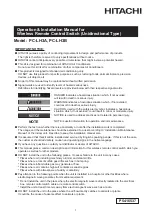
4.  Sending Commands from Controller

The operation commands are sent by 

pressing the required operation switch by 

facing the transmitter of the controller toward 

the receiver of the indoor unit.

(1)  When the commands are sent,


the “ 

 ” indication on the liquid 

crystal display of the controller flashes 

once.

(2)  The indication lamp (yellow) on the 

receiver part of the indoor unit turns 

ON for an instant when the indoor unit 

receives the commands.

ATTENTION:

In case that the indication lamp (yellow) does not turn ON although the commands are sent, the 

commands are not received by the indoor unit.  In such a case, send the commands again.

ATTENTION:

The transmitter of the controller has the vertical directivity to the receiver, and the permissible 

angle for transmitting is within 50

o

.  However, the capable distance for transmitting gets half when 

the transmitting angle is 50

o

, and also get shorter in case that an electronic type light is used in 

the room.

NOTE:

The above figure shows the case of a 4-way cassette type indoor unit.  The figures for other models are 

different partially.

LCD (Liquid Crystal Display) Indication

When viewed from certain angles the LCD can be difficult to read.

The viewing angle ranges from an optimal of 60

o

 down to 30

o

, as 

shown in the diagram on the right.  If the viewing angle is below 

30

o

, the indications not displayed are slightly faded so that makes 

the indication be hardly readable.  It is the characteristics of this 

LCD, which is not abnormality.

60

o

30

o

4

°C

Hi

MODE

RESET

TEMP.

FAN

LOUVER

CANCEL

OFF TIM

E

TIMER

SET

ON TIM

E

AUTO

Receiver Part

Direct Line between

Transmitter and Receiver

Capable Distance for Transmitting:

Max. 6m

Within approx. 50

o

(Directivity)

PC-LH3A

PC-LH3B

Transmitting

indication "    "

flashes once.

Receiver

Indication Lamp (Yellow)

turns ON for an instant.

EMERGENCY

COOL

HEAT

RUN

FILTER DEF

TIMER

Содержание PC-LH3A

Страница 1: ...m the test run whether there is abnormality or not after the installation work is completed The usage and the maintenance should be explained to a user according to Installation Maintenance Manual of the indoor unit Describe to keep this installation manual also l It is assumed that this kit will be installed and serviced by English speaking people If this is not the case the customer should add s...

Страница 2: ...the contents and the number of the parts Name Q ty Remark Wireless Remote Control Switch Controller 1 For Operation Control Holding Bracket 1 For Controller Battery AAA 1 5V Dry Cell 2 For Power Source of Controller Screw 2 For Fixing Holding Bracket onto Wall Slide the cover in the arrow direction with pushing AAA Batteries 2 Do not turn ON the power source unless the preparation for test running...

Страница 3: ...g actual operation Run Stop Switch Operation of the unit can be started or stopped by pressing this switch Fan Speed Switch Press this switch to select the fan speed By repeatedly pressing the button the setting will change sequentially through HIGH2 HIGH MED and LOW Fan speed is fixed at Low for dry operation O Available X Not available HIGH2 is not indicated on PC LH3A Mode Selection Switch By r...

Страница 4: ...g gets half when the transmitting angle is 50o and also get shorter in case that an electronic type light is used in the room NOTE The above figure shows the case of a 4 way cassette type indoor unit The figures for other models are different partially LCD Liquid Crystal Display Indication When viewed from certain angles the LCD can be difficult to read The viewing angle ranges from an optimal of ...

Страница 5: ...oor Units Installed Side by Side NOTE This function is required to set at the receiver side It shall be set according to the installation manual of the receiver kit or the indoor unit Setting of Identifying of Indoor Units Installed Side by Side 1 Press and hold ON TIME switch and OFF TIME switch of the wireless remote control switch simultaneously for 3 seconds The b is indicated on the liquid cr...

Страница 6: ...tion to the following points in case that the controller is installed in a place where there is medical equipment radiating electromagnetic waves 1 Install the controller in a place where electromagnetic waves are not radiated directly toward the electrical box of the indoor unit and the controller 2 Keep a distance more than 3 meters away from the equipment radiating electromagnetic waves the rec...

Страница 7: ...In the test run mode the red lamp RUN of the receiver is turned ON and the green lamp TIMER flashes 0 5 seconds ON 0 5 seconds OFF 2 And then set off timer for 2 hours NOTES 1 In the case that the lamp yellow does not turn ON the controls may not have reached the receiver Send the commands again 2 2 In the case of RPK model TIMER lamp is turned ON without flashing 5 Adjust the angle of the air lou...

Отзывы: