background image

EN

3  ELECTRICAL WIRING

!

D A N G E R

Always make sure to turn off the power of the indoor unit when performing electrical wiring work. 

Performing electrical wiring work with the power turned on can damage the circuit boards of the 

indoor unit and the remote control switch.

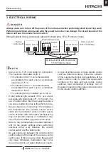
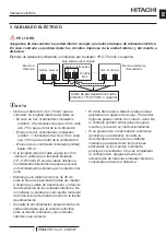
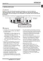
Wiring Example (Using a twist pair cable with shield tube: 1P-0.75 mm2 or more)

REMOCON

A

REMOCON

B

REMOCON

A

REMOCON

B

3 4

Remote 

control switch

Remote control 

switch (Subsidiary)

Electrical box of unit

Terminal board 2

M3.5 

screws

Twist pair cable with shield tube: 

1P-0.75mm

2

 or more

?

N O T E

•  Use a 0.3 to 0.75 mm2 cable for connection. 

The maximum total cable length is:

 - If 3 controllers (Unit + 2 zone thermostats) 

are installed: 25 m each one, for a combined 

maximum of 75 m.

 - If 2 controllers (Unit + 1 zone thermostats) 

are installed: 50 m each one, for a combined 

maximum of 100 m.

 - If 1 controller (Unit) is installed: up to 100 m.

•  If total cable length exceeds 30 m, use a twist 

pair cable with shield tube (1P - 0.75 mm2). The 

use of cables other than those specified above 

can cause malfunction due to the effect of noise.

•  Keep a clearance of more than 30 cm between 

the transmission line (remote control switch 

cable and transmission wires) and the power 

source of indoor units. Otherwise, the heat pump 

may not operate properly or malfunction may 

occur due to the effect of power source noise.

•  Refer to the documentation provided with each 

unit for the proper settings when performing 

electrical wiring work between the remote 

control switch and the indoor units. 

•  No gap shall exist between the remote control 

switch cable and the hole of the remote control 

switch case.  If there is a gap, cover the gap with 

vinyl tape. Otherwise, malfunction may occur 

due to the entrance of water droplets or insects.

•  In case of setting up two or more remote control 

switches (Main and Subs), follow the contents 

of the supplied technical documentation of the 

indoor units in order to select the appropriate 

functions in the main and sub remote control 

switches. Upon completion of settings, turn off 

the power supply of all the indoor units connected 

to the remote control switches.

Electrical Wiring

PMML0577 rev.0 - 09/2021

3

Содержание PC-ARFH2E

Страница 1: ...rev 0 09 2021 INSTRUCTION MANUAL ADVANCED COLOR WIRED REMOTE CONTROLLER MODELS PC ARFH2E INSTRUCTION MANUAL MANUAL DE INSTRUCCIONES BEDIENUNGSANLEITUNG MANUEL D INSTRUCTIONS MANUALE DI ISTRUZIONI EN ES DE FR IT ...

Страница 2: ......

Страница 3: ...den die jeweils neuesten Innovationen präsentieren kann Sämtliche Anstrengungen wurden unternommen um sicherzustellen dass alle technischen Informationen ohne Fehler veröffentlicht worden sind Für Druckfehler kann Hitachi jedoch keine Verantwortung übernehmen da sie außerhalb ihrer Kontrolle liegen FR Les caractéristiques publiées dans ce manuel peuvent être modifiées sans préavis Hitachi souhaita...

Страница 4: ...rmément aux normes et réglementations locales ou nationales en vigueur dans le respect de l environnement En raison du frigorigène de l huile et des autres composants contenus dans le système de climatisation son démontage doit être effectué par un installateur professionnel conformément aux règlementations en vigueur AT T E N Z I O N E Indicazioni per il corretto smaltimento del prodotto ai sensi...

Страница 5: ...Personen Produkt oder Sachschaden verursachen KÖNNEN ATTENTION Utilisation dangereuse ou sans garantie qui PEUT provoquer des blessures ou des dommages au produit ou aux biens ATTENZIONE Pericoli o azioni pericolose che POTREBBERO provocare lesioni fisiche minori o danni al prodotto o ad altri beni NOTE The text following this symbol contains information or instructions that may be of use or that ...

Страница 6: ...2 INSTALLATION 3 KABELANSCHLUSS 4 SCHALTERNAMEN UND FUNKTIONEN 5 HAUPT ANSICHT INDEX 1 CONSIGNES DE SÉCURITÉ 2 INSTALLATION 3 CÂBLAGE ÉLECTRIQUE 4 NOMS ET FONCTIONS DES TOUCHES 5 VUE PRINCIPALE INDICE 1 PRECAUZIONI PER LA SICUREZZA 2 INSTALLAZIONE 3 CABLAGGIO ELETTRICO 4 NOMI E FUNZIONI DEI TASTI 5 VISTA PRINCIPALE EN English Original version ES Español Versión traducida DE Deutsch Übersetzte Vers...

Страница 7: ... v A A B C D E F iv i 121 120 16 5 21 5 ii A B C iii 50 mm G H I B A J vii viii K vi B C D B A E F ...

Страница 8: ......

Страница 9: ...ing standards may be applicable if local regulations are not in force International Organization for Standardization ISO5149 or European Standard EN378 or Japan Standard KHKS0010 This appliance must be used only by adult and capable people having received the technical information or instructions to handle it properly and safely Children should be supervised to ensure that they do not play with th...

Страница 10: ... Attach the stopper plastic band to the cable at the inner side of the draw out hole vi B Cable C Band stopper Field supplied D Draw out hole E Lead the cable with its sheath peeled through the groove F Peel the insulation at the end of the cable and clamp the M3 solderless terminals field supplied When Using Junction Box Prepare the optional field supplied Implanted Junction Box Feed the cable th...

Страница 11: ...he use of cables other than those specified above can cause malfunction due to the effect of noise Keep a clearance of more than 30 cm between the transmission line remote control switch cable and transmission wires and the power source of indoor units Otherwise the heat pump may not operate properly or malfunction may occur due to the effect of power source noise Refer to the documentation provid...

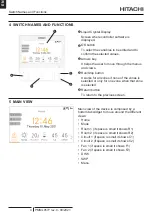
Страница 12: ... selected or only for one zone when that zone is selected Return button To return to the previous screen 5 MAIN VIEW Main view of the device is composed by a bottom tab widget to move around the different views Home Mode Room 1 if space is small it shows R1 Room 2 if space is small it shows R2 Circuit 1 if space is small it shows C1 Circuit 2 if space is small it shows C2 Fan 1 if space is small i...

Страница 13: ...técnico del sistema deberán cumplir con la normativa local y de seguridad En caso de que no exista reglamento local se podrán aplicar las siguientes normas Organización Internacional para la Normalización ISO5149 o Norma Europea EN378 o Norma Japonesa KHKS0010 Este dispositivo debe utilizarlo únicamente un adulto o una persona responsable que haya recibido formación o instrucciones técnicas sobre ...

Страница 14: ...el orificio perforable vi B Cable C Bridadetope suministradaporelinstalador D Orificio perforable E Conduzca el cable con la vaina pelada a través de la ranura F Pele el extremo del cable y fije sin soldar los terminales M3 suministrado por el instalador Cuando el cable del mando a distancia este empotrado Prepare la caja eléctrica suministrada por el instalador Alimente el cable a través del cond...

Страница 15: ...indado 1P 0 75mm2 El uso de cables distintos a los detallados anteriormente puede provocar un funcionamiento anómalo por los efectos del ruido Mantenga una distancia de más de 30 cm entre la línea de transmisión cable del mando a distancia y cables de transmisión y la fuente de alimentación de las unidades interiores De lo contrario la bomba de calor podría funcionar de forma incorrecta debido al ...

Страница 16: ...eccionada Botón Volver Vuelve a la pantalla anterior 5 VISTA PRINCIPAL La vista principal del dispositivo dispone de una pestaña inferior que le permitirá desplazarse entre distintas imágenes Inicio Modo Habitación 1 si el espacio es pequeño muestra H1 Habitación 2 si el espacio es pequeño muestra H2 Circuito 1 si el espacio es pequeño muestra C1 Circuito 2 si el espacio es pequeño muestra C2 Vent...

Страница 17: ...Sicherheitsnormen erfüllen Die folgenden Normen können ggf angewandt werden wenn keine örtlichen Vorschriften gelten Internationale Organisation für Standardisierung ISO5149 oder Europäische Norm EN378 oder Japanische Norm KHKS0010 Dieses Gerät darf nur von Erwachsenen und befähigten Personen betrieben werden die zuvor technische Informationen oder Instruktionen zu dessen sachgemäßer und sicherer ...

Страница 18: ...nseite der Abzugsbohrung an vi B Kabel C Stopper nicht mitgeliefert D Abzugsbohrung E Führen Sie das Ende des Kabels an dem Sie die Ummantelung entfernt haben durch den Schlitz F Entfernen Sie die Isolierung am Ende des Kabels und klemmen Sie die lötfreien Klemmen M3 nicht mitgeliefert an Bei Verwendung eines Schaltkastens Bereiten Sie den optionalen nicht mitgelieferten Schaltkasten eingesetzt vo...

Страница 19: ... angegebenen kann zu Fehlfunktionen infolge der Geräuschentwicklung führen Sorgen Sie für einen Abstand von über 30 cm zwischen der Übertragungsleitung Fernbedienungskabel und Übertragungskabel und dem Stromversorgungskabel von Innengeräten Andernfalls wird die Wärmepumpe möglicherweise nicht ordnungsgemäß funktionieren oder es treten Störungen durch Stromversorgungsgeräusche auf Für die Durchführ...

Страница 20: ...ewählt wurde Zurück Taste Zur Rückkehr zum vorherigen Bildschirm 5 HAUPT ANSICHT Die Hauptansicht des Geräts besteht aus einem unteren Registerkarten Widget mit dem Sie zwischen den verschiedenen Ansichten wechseln können Startseite Modus Raum 1 wenn der Raum klein ist wird R1 angezeigt Raum 2 wenn der Raum klein ist wird R2 angezeigt Kreislauf 1 wenn der Raum klein ist wird HK1 angezeigt Kreislau...

Страница 21: ...é devront respecter les réglementations et normes de sécurité En absence de réglementation locale on pourra appliquer les normes suivantes Organisation internationale de normalisation ISO5149 ou les normes européennes EN378 ou japonaises KHKS0010 Cet équipement ne peut être utilisé que par des personnes adultes ou compétentes ayant reçu des informations ou des instructions techniques pour manipule...

Страница 22: ...orifice de sortie vi B Câble C Butée fournie sur site D Orifice de sortie E Insérez le câble en passant l extrémité dénudée à travers la rainure F Retirez la gaine isolante à l extrémité du câble et serrez les bornes sans soudures M3 fournies sur site Si vous utilisez une boîte de commutation Préparez la boîte de commutation intégrée optionnelle fournie sur site Introduisez le câble dans le condui...

Страница 23: ...5 mm2 L utilisation d un câble autre que le câble indiqué précédemment peut entraîner des dysfonctionnements en raison des effets du bruit Maintenez une distance supérieure à 30 cm entre la ligne de transmission câble de la télécommande et câbles de transmission et la source d alimentation des unités intérieures Sinon la pompe à chaleur pourrait ne pas fonctionner correctement à cause du bruit de ...

Страница 24: ...lle est sélectionnée Bouton retour Pour retourner à l écran antérieur 5 VUE PRINCIPALE La vue principale de l appareil est composée d un widget d onglet inférieur permettant de se déplacer dans les différentes vues Page d accueil Mode Zone 1 si l espace est petit il affiche Z1 Zone 2 si l espace est petit il affiche Z2 Circuit 1 si l espace est petit il affiche C1 Circuit 2 si l espace est petit i...

Страница 25: ...n materia di sicurezza Qualora non fossero in vigore normative locali specifiche saranno applicate le seguenti norme Organizzazione Internazionale per la Standardizzazione ISO5149 o Norma Europea EN378 o Norma Giapponese KHKS0010 Questo dispositivo deve essere utilizzato unicamente da persone adulte competenti alle quali siano state fornite informazioni tecniche o istruzioni atte a garantire un us...

Страница 26: ...sul cavo all interno del foro di passaggio vi B Cavo C Fascetta fermacavi non in dotazione D Foro di passaggio E Rimuovere il rivestimento dal cavo e farlo passare attraverso la scanalatura F Rimuovere l isolante all estremità del cavo e fissare i morsetti non saldati M3 mediante l apposita fascetta non in dotazione Con uso di una scatola di giunzione Preparare la scatola di giunzione opzionale no...

Страница 27: ...doppino schermato 1P 0 75mm2 L utilizzo di cavi diversi da quelli indicati sopra può causare un funzionamento anomalo dovuto all effetto del rumore Mantenere una distanza superiore a 30 cm tra la linea di trasmissione cavo del controllo remoto e cavi di trasmissione e quella di alimentazione delle unità interne In caso contrario la pompa di calore potrebbe non funzionare in modo corretto o potrebb...

Страница 28: ... quella Pulsante indietro Per tornare allo schermo precedente 5 VISTA PRINCIPALE In basso nella vista principale del dispositivo c è un elenco con varie opzioni di visualizzazione tra cui è possibile spostarsi Pagina iniziale Modalità Zona 1 se c è poco spazio verrà visualizzato A2 Zona 2 se c è poco spazio verrà visualizzato A2 Circuito 1 se c è poco spazio verrà visualizzato C1 Circuito 2 se c è...

Страница 29: ......
Страница 30: ...n Johnson Controls Hitachi Air Conditioning Spain S A U Ronda Shimizu 1 Políg Ind Can Torrella 08233 Vacarisses Barcelona Spain Copyright 2021 Johnson Controls Hitachi Air Conditioning Spain S A U All rights reserved ...

Отзывы: