5
DW3
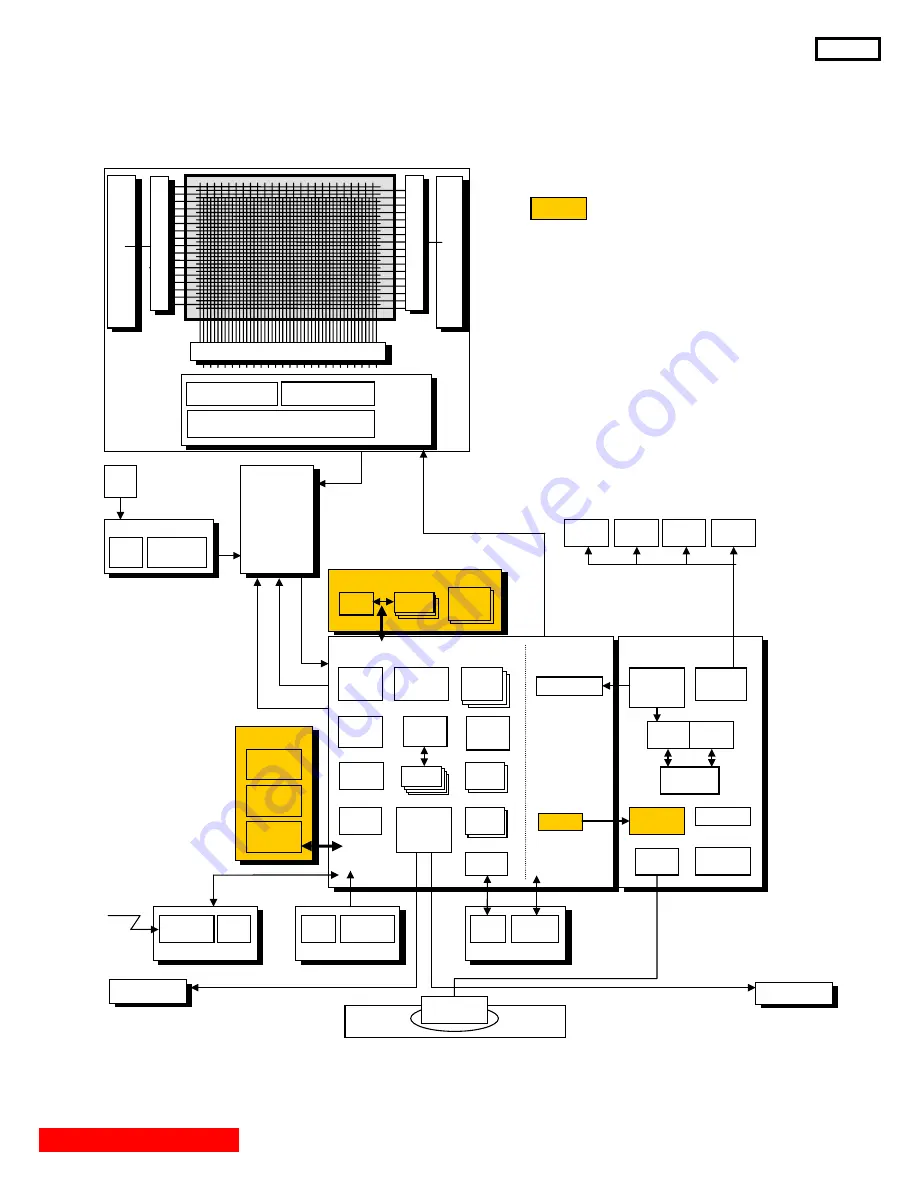
BLOCK DIAGRAM
For P50X901, P50V701 and P50S601.
X-SUS
Y SUS
Driver Controller
LVDS Receiver Signal Controller
Data Controller
LOGIC
Address Driver
Scan
Drive
r
Scan
Drive
r
PDP
Panel
Module
Speaker L
Vcego
Vsago
Stand
Speaker R
Remote
Control
LED PWB
IR
Receiver
LED
RGB
(LVDS)
CPUgo
PDPgo
Power2
Power1
SD PWB
SD/MMC
Card I/F
HDMI
I/F
POD PWB
POD
Card I/F
DC-DC
(POD-Vcc)
PLD
(Oberon)
FAN
FAN
Control PWB
Key
SW
A/V
Pin Jack
Filter PWB
Main
Power SW
Fuse
Power
Supply
Unit
AC
Inlet
FC8 PWB
DC-DC
Conv.
FC8
DDR2
Main-Digital PWB
Sub
Micro
Audio
DSP
Seine2
A-chip
Seine2
D-chip
VCXO
PLL
Audio
PWM
PLD
(Nereid)
DC-DC
Conv.
Audio
ADC
DDR2
Digital
Audio
Amplifier
Audio
DAC
HDMI
Demodulator
UEI
Terminal PWB
IR-Blaster
Driver
OPT-Audio
Output
RS-232C
Video
SW
A/V
Pin Jack
Audio
SW
Motor
Driver
Reg.
For FAN
Digital/
Analog
Tuner
AC-CLK
FAN
FAN
P50X901, P50V701 only.
Содержание P50S601/DW3F
Страница 10: ...FINAL WIRING DIAGRAM FOR P50V701 AND P50S601 DW3 9 TABLE OF CONTENTS ...
Страница 11: ...FINAL WIRING DIAGRAM P50X901 DW3 10 TABLE OF CONTENTS ...
Страница 49: ......


