background image

--- 27 ---

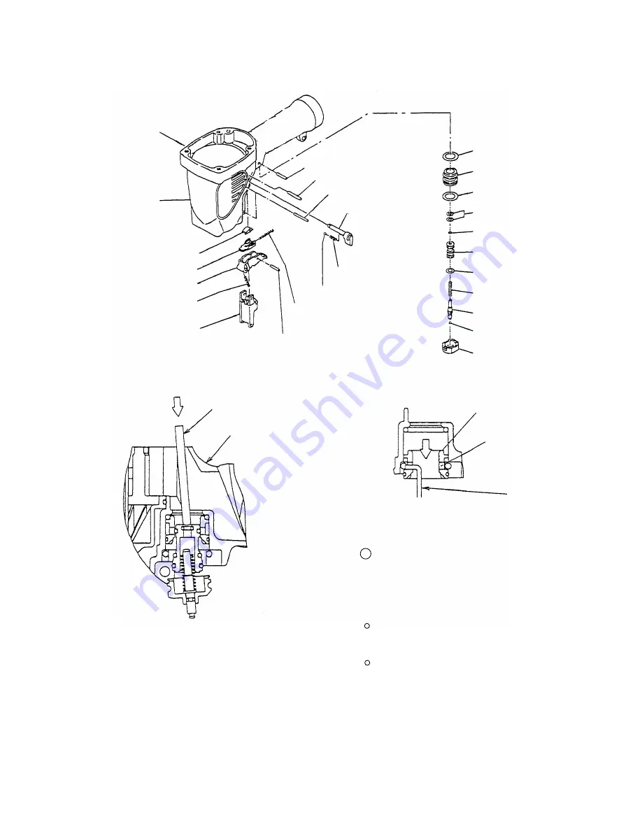
  3  Insert a hooked wire into the hole of Valve

Bushing (B) [67] as shown in Fig. 19 and take

out Valve Bushing (B) [67] being careful not to

scratch the inside of Valve Bushing (B) [67].

Be careful not to scratch Valve Piston (B) [70]

and Valve Bushing (B) [67].

Do not pull out the tip of Plunger (A) [73] with

pliers or other tools.

Lock Knob [61]

Body [23]

Trigger Arm (B) [43]

Trigger [45]

Valve Bushing (B) [67]

Head Valve O-ring
(I.D 16.8) [66]

O-ring (S-18) [68]

O-ring (I.D 8.8) [69]

Trigger Piece [41]

Roll Pin D3 x 28 [60]

Lock Spring [63]

Pushing Lever Guide [47]

Trigger Spring [46]

Roll Pin D3 x 28 [60]

Roll Pin D3 x 22 [59]

Retaining Ring (E-type)
for D4 Shaft [21]

Fig. 17 Disassembly and reassembly of the control valve section

Fig. 18

Fig. 19

Steel Ball D3.175 [62]

Spring [42]

Roll Pin D2.5 x 16 [44]

Valve Piston (B) [70]

O-ring (S-4) [55]

O-ring (I.D 11) [71]

Plunger Spring [72]

O-ring (I.D 1.8) [74]

Plunger (A) [73]

Valve Bushing (A) [75]

Rod

Body [23]

Valve Bushing (B) [67]

Hole

Wire

Содержание NV 65AF3

Страница 1: ...COIL NAILER NV 65AF3 LIST No E005 Aug 2002 POWER TOOLS TECHNICAL DATA AND SERVICE MANUAL SPECIFICATIONS AND PARTS ARE SUBJECT TO CHANGE FOR IMPROVEMENT N MODEL NV 65AF3 ...

Страница 2: ...ERVICE MANUAL a symbol s is are used in the place of company name s and model name s of our competitor s The symbol s utilized here is are as follows Symbols Utilized Competitors Company Name Model Name MAX CN565S S MAKITA AN611 C SENCO SCN55S Q ...

Страница 3: ...10 7 3 Related Laws and Regulations 10 8 MECHANISM AND OPERATION PRINCIPLE 11 8 1 Mechanism 11 8 2 Operation Principle 14 9 TROUBLESHOOTING GUIDE 16 9 1 Troubleshooting and Correction 16 9 2 Possible Causes and Corrections of Air Leakage 21 10 DISASSEMBLY AND REASSEMBLY 24 10 1 General Precautions in Disassembly and Reassembly 24 10 2 Disassembly and Reassembly of the Output Section 25 10 3 Disass...

Страница 4: ... to minimize the exhaust sound and blowing dust In addition the pop out magazine allows easy nail loading from the top of the magazine thanks to the tiltable nail holder Please expand the sales of the new Model NV 65AF3 on Oceania market 3 APPLICATIONS Floor and wall framing Truss and window built up Subflooring and roof decking 4 SELLING POINTS Lightweight only 1 9 kg 4 2 lbs Reduce exhaust press...

Страница 5: ...y PT 1 4 Japanese Standard accessories Weight 200 400 nails 1 coil Air inlet Air plug Packaging dimensions Length x height x width Packaging 355 mm x 410 mm x 170 mm 13 x 16 5 32 x 6 11 16 Carrying case Eye protector Oiler Nose cap 5 SPECIFICATIONS 5 1 Specifications Reciprocating piston type Model Driving system NV 65AF3 Operating pressure 5 8 5 kgf cm2 Gauge pressure 70 120 psi 4 9 8 3 bar Lengt...

Страница 6: ...e shown below CAUTION Ensure that nails are as specified in Fig 1 Other nails will cause clogging of nails and subsequent damage to the nailer 5 mm 0 197 38 mm 1 1 2 Min Fig 1 Dimensions of nails Max 6 mm 0 236 2 8 mm 0 110 2 4 mm 0 094 4 8 mm 0 189 32 mm 1 1 4 Min Max 6 mm 0 236 65 mm 1 1 2 2 8 mm 0 110 2 1 mm 0 083 Wire collated nails Sheet collated nails 57 mm 2 1 4 ...

Страница 7: ...0 787 D2 D1 61 5 2 421 118 4 645 H Fig 3 Dimensions of sheet collated nails 32 57 1 1 4 3 1 4 45 65 1 3 4 2 1 2 L 2 1 2 3 0 083 0 090 2 5 2 8 0 099 0 110 d Type B A 0 6 0 024 19 0 748 37 5 1 476 d1 L1 L2 65 72 H 0 7 0 028 12 0 472 24 0 945 22 30 0 866 1 181 D1 118 MAX 4 645 MAX D2 6 or 8 0 236 or 0 315 ...

Страница 8: ...e and the nailing energy required for driving the nail flush Air pressure which exceeds the intersecting point between the nailer output energy and the required nailing energy for driving the nail allows the nail to be fully driven For example when driving a nail of 2 5 mm dia x 65 mm length 0 099 x 2 1 2 into a workpiece of hemlock with the Model NV 65AF3 a pressure of about 6 bar 6 1 kgf cm2 87 ...

Страница 9: ...ovided Auto contact single Dial Aggressive Not provided Provided Piston ring Provided Provided Sheet 38 57 2 4 2 8 5 0 6 0 2 6 kg 5 8 lbs 267 10 1 2 327 12 7 8 Side open 350 Wire 32 65 Not provided Not provided Contact Plain Not provided Not provided O ring Provided Not provided Sheet 32 65 4 5 8 5 kgf cm2 65 120 psi 4 4 8 3 bar 2 2 kg 4 9 lbs 332 13 1 16 317 12 15 32 1 8 ltr nail Side open 200 40...

Страница 10: ...pth is changed 1 mm with each rotation of the adjuster Do not push up the pushing lever when turning the adjuster Place the lock lever in FREE position when driving nails 6 3 Reduction of Exhaust Pressure with Muffler Comparison of blowing dust The area where concrete dust is blown is shown in black Conditions Nailed 5 times at 0 69 Mpa 7 kgf cm2 Used concrete dust NV 65AF3 Testing method Actual e...

Страница 11: ...2 3 Pull the trigger Depress the pushing lever Depress the pushing lever Driven Driven Nail driving Nail driving 2 Precautions for using dual action trigger Nails are not driven even if the pushing lever is pushed against the workpiece again with the trigger pulled in the single sequential actuation mode To drive nails continuously remove finger from the trigger and operate according to the proced...

Страница 12: ...performance It is recommended to lubricate the Model NV 65AF3 one or two times per month Supply 5 10 drops of lubricant into the air plug on the Model NV 65AF3 When not in use for an extended period supply lubricant and perform idle driving two or three times to lubricate the inside entirely then apply a thin coat of lubricant to the steel parts to avoid rusting Usable lubricant is specified in th...

Страница 13: ... guidance to the customers during sales promotion 7 2 Warning Label Each Model NV 65AF3 unit is provided with a Warning Label illustrated below which lists basic safety precautions in its use Carefully ensure that the customers fully understand and follow these precautions before using the tool 7 3 Related Laws and Regulations As nailers and staplers are designed to instantaneously drive nails and...

Страница 14: ...ody and exhaust cover have been newly designed for greater power output In addition the piston driver blade cylinder and cylinder plate have been newly designed to lengthen the piston stroke Control valve section Trigger A trigger pin valve bushing A valve piston B and plunger A have been newly designed for dual action trigger Note that these parts are not interchangeable with those of the Model N...

Страница 15: ...body Engaged largely It is not disengaged Trigger arm B is disengaged from the pushing lever C Protrusion Trigger arm B is not pushed 1 Depress the pushing lever 1 Pull the trigger Trigger 2 Pull the trigger 2 Depress the pushing lever Driving operation The pushing lever is lowered by lifting the main body The protrusion is in front of plunger A and it is not caught by plunger A Not driven 3 Even ...

Страница 16: ...ade Protector A Cap Feeder Nose Dust Cap Control valve section Body Hook Adjuster Valve Bushing B Valve Bushing A Plunger A Valve Piston B Pushing Lever Nail Holder Magazine Nail Guide Driving Hole Magazine Cover Cross section A A Feed Piston Guide Lock Feeder Fig 7 Construction Driving section Output section Cylinder Plate Magazine section ...

Страница 17: ...rough air passage A 3 The air pressure applied against the lower surface of the head valve soon exceeds the force of the head valve spring and pushes the head valve up The head valve is pushed fully upward by the compressed air and seals the upper surface of the exhaust cover and the head valve 4 When the head valve is pushed up the compressed air flows rapidly into the cylinder and pushes down th...

Страница 18: ... the cylinder is opened to the atmosphere 2 When the head valve seals the upper surface of the cylinder the compressed air accumulated in the return air chamber passes through air passage C presses on the lower surface of the piston and forces the piston to return upward to its original position Also the compressed air above the piston is exhausted through the head valve hole 3 The compressed air ...

Страница 19: ...r pressure is too low Air passage is clogged with broken pieces of piston bumper etc Feed piston chamber contains foreign matter such as broken pieces of piston bumper etc Check that the magazine is collectly loaded with specified nails Remove the feed piston and check the feed piston sliding surface of the nose Use specified nails Remove the abnormal nails and load the nailer with proper nails Ch...

Страница 20: ...e Inspection method Remedy 1 Nails cannot be driven continued Output section piston driver blade etc Air pressure is too low Piston ring is abnormal worn or damaged Piston bumper is abnormal O ring in the cylinder is abnormal removed deformed or damaged Driver blade is abnormal deformed burrs or damaged Adjust the air pressure to 5 8 5 kgf cm2 4 9 8 3 bar 70 120 psi Open the nail guide and perform...

Страница 21: ...ial is beyond its applicable range Check if a nail is bent even when driven into soft wood Check that the driver blade tip is not abnormally worn Replace the abnormal part Turn the adjuster lower lower the pressure See item 1 Driver blade is worn Replace the part Adjust air pressure to 5 8 5 kgf cm2 4 9 8 3 bar 70 120 psi Nailer cannot be used because the material is beyond its applicable range Ch...

Страница 22: ...llation pitch Sheet collated nails Collating sheets are abnormal deformed or broken Nails are removed from the sheets Use specified nails Remove the abnormal nails and load the nailer with proper nails Check if the specified nails are used Check the nails as follows Head valve sliding surface is abnormal seized or damaged or lubrication is needed Disassemble the output section and check the piston...

Страница 23: ...ring or feeder spring is abnormal damaged fatigued or removed 4 Nails jam continued Open the nail guide and check the position of the feeder claw Replace the abnormal part Body Nail guide section Nail guide section is abnormal See item 1 Nail guide section Perform idle or actual driving to check if the driver blade is returned completely Nails may be jammed if driven at a high pressure and high sp...

Страница 24: ...air procedure 1 Check the points of the following parts marked by an asterisk for abnormal condition 2 Next check the seal parts marked with a double circle for wear flaws or damage 3 And then check other places a b A B C D F G E F G c d e f H g h Cross section A A Control valve section ...

Страница 25: ...the Cylinder 17 Abnormality deformation crack and or damage of the sections e and f in the Piston Bumper 25 Deformation of the Piston H 20 The deformation of driver blade abnormality in sealed faces The deformation of the face f of the Body 23 Abnormality wear deformation breakage and or scratches in the O Ring S 46 15 E Feed piston Abnormality wear breakage and or scratches in the O ring P 21 78 ...

Страница 26: ...s turned off When the Trigger is turned on G Control valve 2 H Cap Abnormality wear breakage and or scratches in the O ring I D 1 8 74 of Plunger A 73 Abnormality deformation and or scratches of the sliding face of Plunger A 73 in Valve Bushing A 75 Abnormality wear breakage and or scratches in the O ring S 4 55 in the inside of Valve Piston B 70 Abnormality deformation and or scratches of the sli...

Страница 27: ...n Disassembly and Reassembly Apply grease Nippeco SEP 3A Code No 930035 to the O rings and O rings sliding portions When installing the O rings be careful not to damage the O rings and prevent dirt entry Oil required Hitachi pneumatic tool lubricant 1 oz 30 cc Oil feeder Code No 877153 4 oz 120 cc Oil feeder Code No 874042 1 quart 1 ltr Can Code No 876212 If Gasket A 8 is damaged replace it and ch...

Страница 28: ...cing the stopper to the Piston Bumper 25 side Mount the Cylinder Plate 14 to the Body 23 aligning the stopper groove of the Cylinder Plate 14 with the rib of the Body 23 10 2 Disassembly and Reassembly of the Output Section 1 Disassembly and reassembly of the Exhaust Cover 7 Head Valve A 12 Piston H 20 Cylinder 17 etc See Figs 12 13 and 14 Hex Socket Hd Bolt M6 x 12 1 Plate 2 Head Bumper 9 Gasket ...

Страница 29: ...d Valve Spring 10 10 3 Disassembly and Reassembly of the Control Valve Section Tools required Roll pin pullers 3 mm dia and 2 5 mm dia a Disassembly Fig 17 Remove the Retaining Ring E type for D4 Shaft 21 to remove the lock knob Pull out the two Roll Pins D3 x 28 60 with the roll pin puller 3 mm dia Then the trigger unit can be removed from the Pushing Lever Guide 47 The trigger unit can be disass...

Страница 30: ...rigger 45 Valve Bushing B 67 Head Valve O ring I D 16 8 66 O ring S 18 68 O ring I D 8 8 69 Trigger Piece 41 Roll Pin D3 x 28 60 Lock Spring 63 Pushing Lever Guide 47 Trigger Spring 46 Roll Pin D3 x 28 60 Roll Pin D3 x 22 59 Retaining Ring E type for D4 Shaft 21 Fig 17 Disassembly and reassembly of the control valve section Fig 18 Fig 19 Steel Ball D3 175 62 Spring 42 Roll Pin D2 5 x 16 44 Valve P...

Страница 31: ... Roll Pin D3 x 22 59 If the roll pins are driven forcedly in spite of the roll pin groove of Valve Bushing A 75 does not align with the roll pin hole of the Body 23 the outside of Valve Bushing A 75 will be damaged and disassembly and reassembly will be impossible Protrusion of Trigger Arm B 43 Fig 21 Trigger 45 Spring 42 Apply grease to the groove Valve Bushing A 75 Roll pin groove Seal grease in...

Страница 32: ...y of the Magazine Section 1 Disassembly and reassembly of the magazine section a Disassembly Fig 24 Loosen the Hex Socket Hd Bolt M5 x 20 101 and the Nylon Nut M5 36 and remove the Sleeve 85 Deform Pushing Lever Cover A 86 using a flat blade screwdriver and disengage it from the Nose 27 Loosen the Machine Screw M5 x 35 Black 65 of the Body 23 Then the magazine section and the Hook 64 can be remove...

Страница 33: ... Pin D2 5 x 12 98 Hex Socket Hd Bolt M5 x 20 101 Spring 100 Nail Holder 97 Holder Shaft 99 Ratchet Spring 96 Fig 24 Disassembly and reassembly of magazine section Engage the protrusion of the Magazine 90 in the hole of the Cover 111 Body 23 Engage Hook 64 Pin 89 b Reassembly Disassembly procedures should be followed in the reverse order Note that the protrusion of the Magazine 90 is engaged in the...

Страница 34: ...nts When mounting the Holder Shaft 99 to the Magazine 90 check that the Spring 100 is securely inserted between the concave portion of the Magazine 90 and the convex portion of the Holder Shaft 99 then insert the Pin 89 Fig 25 Check that the two Feeder Shaft Rings 91 are securely inserted into the grooves of the Pins 89 2 pcs Be careful not to lose the Feeder Shaft Rings 91 Check the following aft...

Страница 35: ...ver C 49 Adjuster 50 Piston Bumper 25 Feed Spring 80 Nose 27 Roll Pin D4 x 16 29 Feeder Spring 32 Feeder 33 Roll Pin D2 x 16 51 Adjuster Spring 52 Adjuster Plate B 53 Adjuster Plate A 54 O ring S 4 55 Pushing Lever B 56 O ring S 5 57 Retaining Ring E type for D3 Shaft 58 O ring P 21 78 Feed Piston 79 Retaining Ring for D28 Hole 84 O ring P 9 77 10 5 Disassembly and Reassembly of the Driving Sectio...

Страница 36: ...toward Adjuster Plate A 54 1 Disassembly and reassembly of Nose 27 Pushing Lever 35 and others a Disassembly Figs 26 and 27 Remove the four Nylock High Tension Bolts M6 x 20 28 Then the Nose 27 Pushing Lever 35 and other parts can be removed b Reassembly Disassembly procedures should be followed in the reverse order Note the following points Apply grease to the O ring S 46 15 and mount it in the g...

Страница 37: ...d Push out the Needle Roller 30 with a roll pin puller 4 mm dia Then the Feeder Arm 31 Feeder 33 and Feeder Spring 32 can be removed b Reassembly Disassembly procedures should be followed in the reverse order Note the following points Before replacing the Piston Bumper 25 clean the passages of the Body 23 and the Nose 27 Fig 29 and the inside of the feed piston chamber Fig 30 If clogged with fragm...

Страница 38: ... flat blade screwdriver and remove the Nail Guide Shaft 102 Then the Nail Guide 105 and other parts can be removed in an assembly Remove the Nylock Hex Socket Hd Bolt M4 x 10 110 and the Nylock Hex Socket Hd Bolt M4 x 12 114 with a hex bar wrench 3 mm Then the Nail Guide Cover 112 Stopper Spring 109 Nail Stopper Spring 104 and Cover 111 can be removed Remove the Shaft Ring 76 from the Guide Lock 1...

Страница 39: ...ON AFTER REASSEMBLY Check that Plunger A 73 moves smoothly Check that the Pushing Lever 35 slides smoothly Push Nail Stopper A 103 and Nail Stopper B 108 with fingers to check that they return securely Check that there is no air leakage from each part Check that the Model NV 65AF3 will not operate only by pulling the Trigger 45 Also check that the Model NV 65AF3 will not operate only by depressing...

Страница 40: ...ger Spring Valve Packing O ring x 3 12 STANDARD REPAIR TIME UNIT SCHEDULES MODEL 10 20 30 40 Fixed Variable NV 65AF3 Work Flow Exhaust Cover Top Cover Packing A Head Valve Spring Head Valve O ring Head Valve A 60 min 50 Cylinder Plate Cylinder Piston Bumper O ring x 3 General Assembly Change Knob Spring C Steel Ball Feeder Arm Feeder Feeder Spring Tail Cover Nail Guide Nail Stopper A Nail Stopper ...

Страница 41: ... 15 25 26 27 28 29 30 31 32 33 34 35 88 36 37 38 39 40 41 42 43 44 45 46 47 48 49 50 51 52 53 54 55 56 57 58 59 60 60 61 62 63 64 65 66 67 68 69 55 70 71 72 73 74 75 36 85 86 87 76 77 78 79 80 81 82 83 84 88 90 91 92 93 94 95 96 97 98 99 76 26 100 101 102 103 104 105 106 107 108 109 110 111 112 113 114 501 502 503 504 22 89 89 91 115 100 ...

Страница 42: ...3 RETAINING RING E TYPE FOR D4 SHAFT 1 22 NAME PLATE 1 23 883 857 BODY 1 24 HITACHI LABEL 1 25 882 873 PISTON BUMPER 1 26 874 436 O RING P 4 2 27 882 875 NOSE 1 28 880 675 NYLOCK HIGH TENSION BOLT M6X20 4 29 949 497 ROLL PIN D4X16 10 PCS 1 30 880 659 NEEDLE ROLLER 1 31 878 132 FEEDER ARM 1 32 882 924 FEEDER SPRING 1 33 883 785 FEEDER 1 34 882 900 PUSHING LEVER COVER B 1 35 882 884 PUSHING LEVER 1 ...

Страница 43: ...1 878 887 O RING I D 11 1 72 878 884 PLUNGER SPRING 1 73 882 921 PLUNGER A 1 74 878 888 O RING I D 1 8 1 75 882 920 VALVE BUSHING A 1 76 880 319 SHAFT RING 2 77 872 645 O RING P 9 1 78 880 330 O RING P 21 1 79 882 673 FEED PISTON 1 80 882 883 FEED SPRING 1 81 877 711 BUMPER 1 82 880 331 FEED PISTON COVER 1 83 878 305 MAGAZINE BUSHING 1 84 939 555 RETAINING RING FOR D28 HOLE 10 PCS 1 85 882 907 SLE...

Страница 44: ... 786 NAIL GUIDE 1 106 880 318 GUIDE LOCK 1 107 880 446 SPRING 1 108 882 680 NAIL STOPPER B 1 109 880 494 STOPPER SPRING 1 110 880 413 NYLOCK HEX SOCKET HD BOLT M4X10 1 111 882 880 COVER 1 112 883 784 NAIL GUIDE COVER 1 113 882 881 SLEEVE B 1 114 880 630 NYLOCK HEX SOCKET HD BOLT M4X12 1 115 882 926 MAGAZINE ASS Y 1 INCLUD 88 100 501 877 153 PNEUMATIC TOOL LUBRICANT 30CC 1 502 875 769 EYE PROTECTOR...

Страница 45: ......

Отзывы: