


--- 45 ---
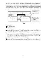
(2) Reassembly
Reassembly procedures should be followed in the reverse order. Note the following points.
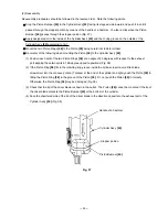
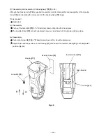
Drop the Piston Bumper
[40]
in the Cylinder Ass'y
[42]
facing its stepped side inward and push it in until it
passes through the stopper portion by means of the handle of a hammer. You feel a click when the Piston
Bumper
[40]
passes through the stopper portion (Fig. 37).
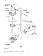
Apply designated oil to the inside of the Cylinder Ass'y
[42]
and the O-ring groove on the outside of the
Cylinder Ass'y
[42]
according to 10-1.
Mount the two Piston Rings
[38]
to the Piston
[39]
being careful not to deform them.
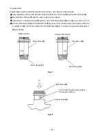
Be careful of the following when mounting the Piston
[39]
to the Cylinder Ass'y
[42]
.
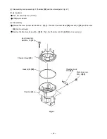
(1) Position each split of the two Piston Rings
[38]
at an angle of 90 degrees with respect to the exhaust
port aligning these two splits in 180-degree opposite positions (Fig. 38).
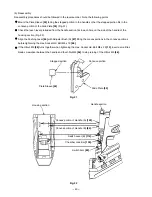
(2) If the Piston Ring
[38]
fits in the retaining ring groove inside the cylinder, insert a small flat-blade
screwdriver into the concave portion (7 places) at the end of the cylinder and lightly push the Piston
[39]
in
fitting the Piston Ring
[38]
in the groove of the Piston
[39]
. Do not push the Piston
[39]
in forcedly.
Otherwise, the Piston Ring
[38]
may be damaged (Fig. 39).
(3) Check that the tip of the driver blade is shown in the outlet. The Piston
[39]
cannot be mounted if the tip of
the driver blade contacts the Piston Bumper
[40]
or the bottom of the cylinder.
(4) Face the chamfered side of the tip of the driver blade in the direction opposite to the exhaust port of the
Cylinder Ass'y
[42]
(Fig. 39).
Cylinder Ass'y
[42]
Handle of a hammer
Piston Bumper
[40]
Stopper portion
Fig. 37
Содержание NR 90GC
Страница 25: ... 22 Fan Clean this area especially Spark plug cable Spark plug Fig 18 ...
Страница 33: ... 30 Handle B 84 Grease application areas Plunger of the fan switch Plunger of the trigger switch Fig 22 ...
Страница 69: ... 66 Fig 58 Lock Bar Spring 102 Fig 59 Ring Tension Plate 113 Switch Lever B 114 ...
Страница 78: ......


