


--- 8 ---
8. MECHANISM AND OPERATION PRINCIPLE
8-1. Mechanism
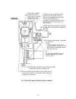
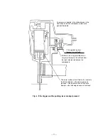
As illustrated in Fig. 3, the Model N 5008AC can be generally divided into four sections:
output section, control valve section, driving section and magazine section.
The driving section (nose and piston) and the magazine section have been newly designed though its basic
construction is the same as that of the Model NT 65A2 (valve section is common to the Model NT 65A2).
Primary differences from the Model NT 65A2 are described below.
Output section ........ The piston (driver blade) has been newly designed according to the shape of the
staple firing gate. Owing to the enlargement of the driver blade, the piston bumper has
been newly designed.
Driving section ........ All the parts have been newly designed for driving staples.
A pushing lever piece is provided to adjust the driving depth of staples with a wrench.
If clogged staples are caused in this section, they can be easily released simply by pulling
the lock lever by hand.
Magazine section .... All the parts have been newly designed for driving staples.
The magazine cover is opened by pulling the staple feeder backward for easy loading or
replacement of staples.
The <Bold> numbers in the figure below correspond to the numbers in "8-2. Operation Principle".
Fig. 3 Construction
Exhaust Vent < 3 >
Return Air
Chamber < 8 >
Driver Blade < 7 >
Cylinder < 6 >
Piston < 4 >
Piston
Bumper < 9 >
Nose <10>
Blade Guide
Pushing Lever
Accumulator < 1 >
Control valve
section
Exhaust Cover
Cylinder Spring <5>
Trigger Valve portion
Grip Rubber
Staple Rail
Magazine Ass'y
Staple Feeder
Magazine section
Safety Valve portion
Driving section
Output section
Exhaust Valve < 2 >
Lock Lever
Pushing Lever Piece
Firing Gate
Handle Arm
Magazine Cover


