Step-by-Step Basic Installation
In
v
e
rt
er Mounting
and Installation
2–20
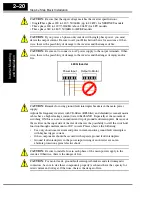
CAUTION:
Be sure that the input voltage matches the inverter specifications:
• Single/Three phase 200 to 240 V 50/60 Hz (up to 2.2kW) for NFEF/NFU models
• Three phase 200 to 240V 50/60Hz (above 2.2kW) for LFU models
• Three phase 380 to 480 V 50/60Hz for HFEF models
CAUTION:
If you power a 3-phase-only inverter with single phase power, you must
derate the output current. Be sure to call your Hitachi distributor for assistence. Other-
wise, there is the possibility of damage to the inverter and the danger of fire.
CAUTION:
Be sure not to connect an AC power supply to the output terminals. Other-
wise, there is the possibility of damage to the inverter and the danger of injury and/or
fire.
CAUTION:
Remarks for using ground fault interrupter breakers in the main power
supply:
Adjustable frequency inverters with CE-filters (RFI-filter) and shielded (screened) motor
cables have a higher leakage current toward Earth GND. Especially at the moment of
switching ON this can cause an inadvertent trip of ground fault interrupters. Because of
the rectifier on the input side of the inverter there is the possibility to stall the switch-off
function through small amounts of DC current. Please observe the following:
•
Use only short time-invariant and pulse current-sensitive ground fault interrupters
with higher trigger current.
•
Other components should be secured with separate ground fault interrupters.
•
Ground fault interrupters in the power input wiring of an inverter are not an
absolute protection against electric shock.
CAUTION:
Be sure to install a fuse in each phase of the main power supply to the
inverter. Otherwise, there is the danger of fire.
CAUTION:
For motor leads, ground fault interrupter breakers and electromagnetic
contactors, be sure to size these components properly (each must have the capacity for
rated current and voltage). Otherwise, there is the danger of fire.
Power Input
Output to Motor
L200
2
Inverter
Содержание L200-002NFE2
Страница 2: ......
Страница 46: ......
Страница 80: ......
Страница 204: ......
Страница 205: ...Inverter System Accessories In This Chapter page Introduction 2 Component Descriptions 3 Dynamic Braking 5 5 ...
Страница 212: ......
Страница 229: ...Glossary and Bibliography In This Appendix page Glossary 2 Bibliography 8 A ...
Страница 280: ......
Страница 281: ...Drive Parameter Settings Tables In This Appendix page Introduction 2 Parameter Settings for Keypad Entry 2 C ...
Страница 293: ...CE EMC Installation Guidelines In This Appendix page CE EMC Installation Guidelines 2 Hitachi EMC Recommendations 6 D ...
Страница 297: ...L2002 Inverter Appendix D D 5 L1 L2 L3 PE L2002 inverter with book type filter M 3 ...

