Using Intelligent Input Terminals
Oper
ations
and Monitor
ing
4–28
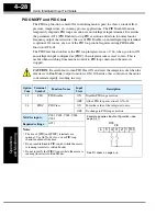
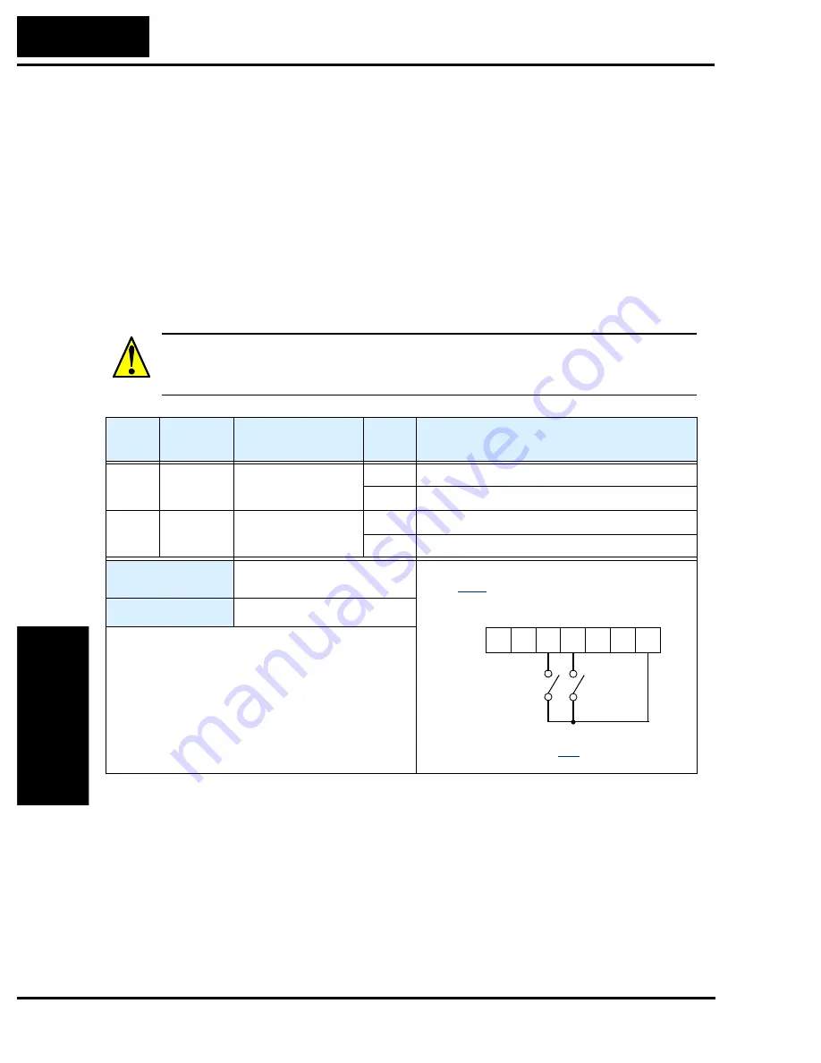
PID ON/OFF and PID Clear
The PID loop function is useful for controlling motor speed to achieve constant flow,
pressure, temperature, etc. in many process applications. The PID Disable function
temporarily suspends PID loop execution via an intelligent input terminal. It overrides
the parameter A071 (PID Enable) to stop PID execution and return to normal motor
frequency output characteristics. the use of PID Disable on an intelligent input terminal
is optional. Of course, any use of the PID loop control requires setting PID Enable
function A071=01.
The PID Clear function forces the PID loop integrator sum = 0. So, when you turn ON
an intelligent input configured as [PIDC], the integrator sum is reset to zero. This is
useful when switching from manual control to PID loop control and the motor is
stopped.
CAUTION:
Be careful not to turn PID Clear ON and reset the integrator sum when the
inverter is in Run Mode (output to motor is ON). Otherwise, this could cause the motor
to decelerate rapidly, resulting in a trip.
Option
Code
Terminal
Symbol
Function Name
Input
State
Description
23
PID
PID Disable
ON
Disables PID loop execution
OFF
Allows PID loop execution if A71=01
24
PIDC
PID Clear
ON
Force the value of the integrator to zero
OFF
No change to PID loop execution
Valid for inputs:
C001, C002, C003, C004,
C005
Required settings:
A071
Notes:
•
The use of [PID] and [PIDC] terminals are
optional. Use A071=01 if you want PID loop
control enabled all the time.
•
Do not enable/disable PID control while the motor
is running (inverter is in Run Mode).
•
Do not turn ON the [PIDC] input while the motor is
running (inverter is in Run Mode).
Example (requires input configuration—see
page
See I/O specs on page
PID
PIDC
1
2
3
4
5
L
PCS
Содержание L200-002NFE2
Страница 2: ......
Страница 46: ......
Страница 80: ......
Страница 204: ......
Страница 205: ...Inverter System Accessories In This Chapter page Introduction 2 Component Descriptions 3 Dynamic Braking 5 5 ...
Страница 212: ......
Страница 229: ...Glossary and Bibliography In This Appendix page Glossary 2 Bibliography 8 A ...
Страница 280: ......
Страница 281: ...Drive Parameter Settings Tables In This Appendix page Introduction 2 Parameter Settings for Keypad Entry 2 C ...
Страница 293: ...CE EMC Installation Guidelines In This Appendix page CE EMC Installation Guidelines 2 Hitachi EMC Recommendations 6 D ...
Страница 297: ...L2002 Inverter Appendix D D 5 L1 L2 L3 PE L2002 inverter with book type filter M 3 ...

