“B” Group: Fine Tuning Functions
Configur
ing
Dr
iv
e P
a
ra
m
e
ters
3–24
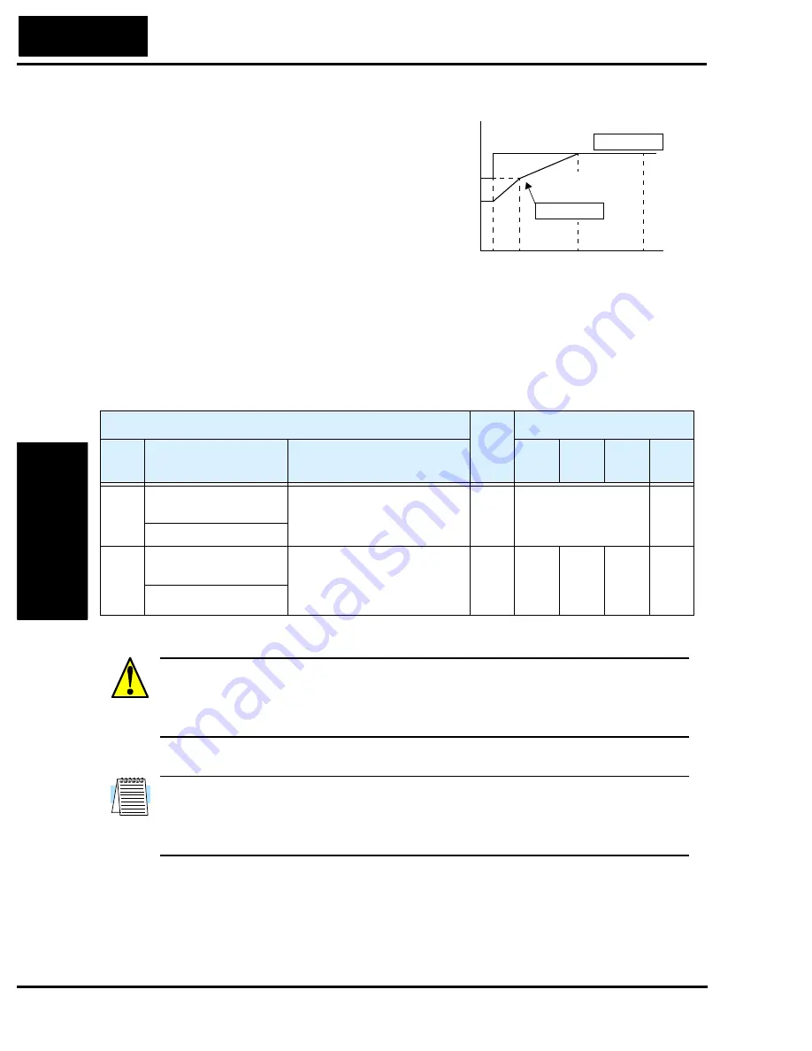
Electronic Thermal Overload Alarm Setting
The thermal overload detection protects the
inverter and motor from overheating due to
an excessive load. It uses a current/inverse
time curve to determine the trip point.
First, use B_13 to select the torque charac-
teristic that matches your load. This allows
the inverter to utilize the best thermal
overload characteristic for your application.
The torque developed in a motor is directly
proportional to the current in the windings,
which is also proportional to the heat generated (and temperature, over time). Therefore,
you must set the thermal overload threshold in terms of current (amperes) for parameter
B_12. The range is 50% to 120% of the rated current for each inverter model. If the
current exceeds the level you specify, the inverter will trip and log an event (error E05) in
the history table. The inverter turns the motor output OFF when tripped.
WARNING:
When parameter B_12, level of electronic thermal setting, is set to device
FLA rating (Full Load Ampere nameplate rating), the device provides solid state motor
overload protection at 115% of device FLA or equivalent. Parameter B_12, level of
electronic thermal setting, is a variable parameter.
NOTE:
For inverter models 005NFE, 011NFE, and 030HFE, the thermal value is less
than the rated amperes (is the same as models 004NFE, 007NFE, and 040HFE respec-
tively). Therefore, be sure to set the electronic thermal overload according to the actual
motor driven by the particular inverter.
Output frequency
Constant torque
Reduced
torque
B_13 = 01
B_13 = 00
Torque
5
20
60
120
Hz
100%
80%
60%
0
“B” Function
Run
Mode
Edit
Defaults
Func.
Code
Name /
SRW Display
Description
–FE
(CE)
–FU
(UL)
–FR
(Jpn)
Units
B_12 Level of electronic
thermal setting
Set a level between 50% and
120% for the rated inverter
current.
✘
Rated current for each
inverter model
*See note
%
E-THM LVL 03.00A
B_13 Electronic thermal
characteristic
Select from two curves, option
codes:
00 ...Reduced torque
01 ...Constant torque
✘
01
01
00
—
E-THM CHAR CRT
Содержание L100 Series
Страница 145: ...Inverter System Accessories In This Chapter page Introduction 2 Component Descriptions 3 Dynamic Braking 5 5 ...
Страница 168: ...Glossary and Bibliography In This Appendix page Glossary 2 Bibliography 8 A ...
Страница 176: ...Drive Parameter Settings Tables In This Appendix page Introduction 2 Parameter Settings for Keypad Entry 2 B ...
Страница 183: ...CE EMC Installation Guidelines In This Appendix page CE EMC Installation Guidelines 2 Hitachi EMC Recommendations 6 C ...
Страница 186: ...CE EMC Installation Guidelines Appendix C C 4 L1 L2 L3 PE M 3 L100 inverter with footprint type filter ...
Страница 187: ...L100 Inverter Appendix C C 5 L1 L2 L3 PE L100 inverter with book type filter M 3 ...


