1000 Brown Rd.
Auburn Hills, MI 48326
248.754.1900
jrautomation.com
Continuous Antenna User Manual - Canada
Prelim 1
Page 10 of 11
Printed: 11/16/22
3:36 PM
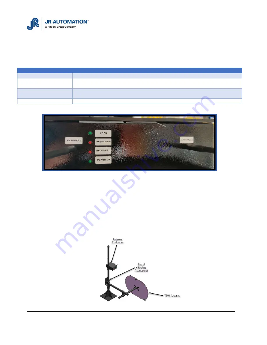
In addition to the external connections, the Antenna Enclosure has 4 indicator LED’s:
LED Description
Function
LF On
Illuminates when the antenna system is transmitting an 125KHz LF signal
Receiver 1
Momentarily flashes whenever a valid UHF packet is received from a TPM valve
stem, on receiver 1 (antenna 1)
Receiver 2
Momentarily flashes whenever a valid UHF packet is received from a TPM valve
stem, on receiver 2 (antenna 2)
Power on
Illuminates when the antenna is supplied with 24VDC
Receiver Antenna Connections & LED's
ANTENNA MOUNTING
The antenna is typically mounted on an adjustable stand that is sold as a separate accessary. The stand also
holds the antenna enclosure, which is mounted on a backplate. Typically, this will be provided by the Automation
System Integrator.


