


8
no
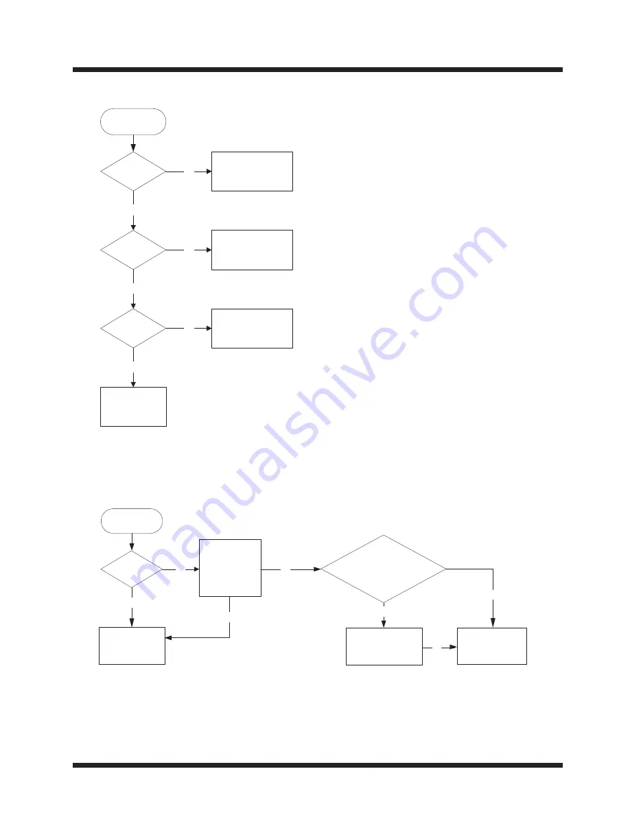
Replace VF1.
Is the voltage
at F+ & F- of
VF1 normal?
Start
Is the voltage
at pin 34 of
PT6311 -24V?
Replace PT6311.
Replace Function
Button PWB Assy
yes
yes
no
SYMPTOM: OUTPUT DISPLAY ABNORMAL
(REVISED)
Is the connection
of Function Button
& Decoder PWB
Assy secure?
Secure the connection
of Function Button
& Decoder PWB Assy.
yes
no
SYMPTOM: OPEN/CLOSE TRAY ABNORMAL
(REVISED)
Start
Does pin 1 of XP1
(Function Button
PWB Assy) output
pulse signal?
Is the voltage at
pin 7 of XP1 5V?
no
yes
(1) XP1 (Function Button PWB)
& XS9 (Decoder PWB) or
(2) Loading Assy & L23
(Decoder PWB)?
Secure the connection
of Function Button &
Decoder PWB Assy.
yes
Replace remote
receiver B1 of
Function Button or
Decoder PWB Assy
Is OSD "open"
showed on the
screen?
Replace Loading
Assy
yes
no
Is the connector broken between
no
no
(To replace Pg 29-39 of SC No. 0015E)
Содержание HTD-K210
Страница 20: ...C S 0 1 2 K D T H No 0015E 1 Copyright Digital Media Systems Group 2006 All rights reserved ...
Страница 34: ...POWER BOARD DIAGRAM 14 AMP BOARD DIAGRAM ...
Страница 35: ...MIC BOARD DIAGRAM 15 2630 USB BOARD DIAGRAM ...
Страница 36: ...DECODER BOARD DIAGRAM TOP 16 ...
Страница 37: ...DECODERBOARD DIAGRAM BOTTOM 17 ...
Страница 71: ...HTD K210 SC No 0015E Copyright Digital Media Systems Group 2005 All rights reserved ...