background image

--- 8 ---

7. PRECAUTIONS IN SALES PROMOTION

In the interest of promoting the safest and most efficient use of the Model H 45SR Electric Hammer by all of our

customers, it is very important that at the time of sale the salesperson carefully ensures that the buyer seriously

recognizes the importance of the contents of the Handling Instructions, and fully understands the meaning of the

precautions listed on the Caution Plate attached to each tool.

7-1. Handling Instructions

Although every effort is made in each step of design, manufacture and inspection to provide protection against

safety hazards, the dangers inherent in the use of any electric tool cannot be completely eliminated.  Accordingly,

general precautions and suggestions for the use of electric power tools, and specific precautions and suggestions

for the use of the Electric Hammer are listed in the Handling Instructions to enhance the safe, efficient use of the

tool by the customer.  Salespersons must be thoroughly familiar with the contents of the Handling Instructions to

be able to offer appropriate guidance to the customer during sales promotion.

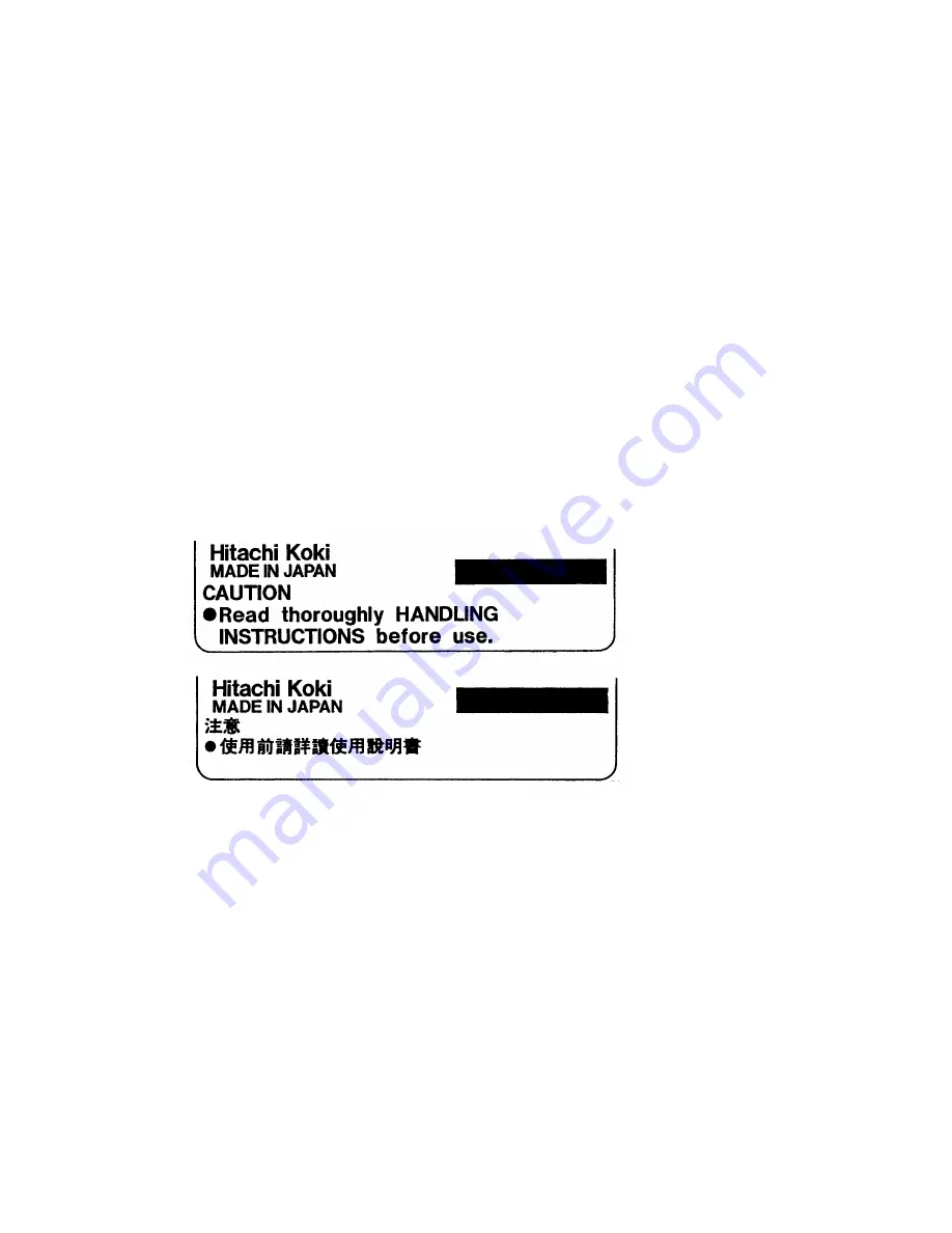
7-2. Caution Plate

The Model H 45SR unit is provided with a Caution Plate (illustrated below) which lists basic safety precautions in

use.  Carefully ensure that the customer fully understands and follows these precautions before using the tool.

      For Australia

For Taiwan

7-3. Grease Replacement

The striking portion and the speed reduction portion of the Model H 45SR respectively use different types of

grease.  Grease replacement is required if the unit is disassembled for maintenance or O-rings become damaged

and worn as described in 7-4.

The striking portion uses special grease.  If the striking portion (inside the cylinder crank case) is disassembled,

thoroughly remove all of the old grease from each part.  On reassembly, insert 53 g (1.9 oz) of new grease into

the cylinder crank case (connecting rod side).  Do not exceed the designated amount of grease.  Excessive

grease insertion may cause reduced striking performance.

The speed reduction portion (inside the gear cover) uses Hitachi Motor Grease No. 29 (Code No. 930035).  The

proper supply volume is 20 g (0.7 oz).  Never use the striking portion special grease in the speed reduction

portion.  Special grease would leak into the motor portion and cause subsequent trouble.

Содержание H 45SR

Страница 1: ...POWER TOOLS TECHNICAL DATA AND SERVICE MANUAL HAMMER H 45SR SPECIFICATIONS AND PARTS ARE SUBJECT TO CHANGE FOR IMPROVEMENT LIST No E464 May 2002 M MODEL H 45SR ...

Страница 2: ...AL DATA AND SERVICE MANUAL a symbol s is are used in the place of company name s and model name s of our competitor s The symbol s utilized here is are as follows Symbols Utilized Competitors Company Name Model Name MAKITA HM0810 C ...

Страница 3: ...Body Jumping 7 7 PRECAUTIONS IN SALES PROMOTION 8 7 1 Handling Instructions 8 7 2 Caution Plate 8 7 3 Grease Replacement 8 7 4 O Ring Replacement 9 8 REFERENCE INFORMATION 9 8 1 Striking Operation 9 8 2 Idling Proof Mechanism 10 8 3 Shock Absorbing Mechanism 10 8 4 Sealed and Dustproof Construction 11 8 5 Vibration Absorbing Construction 11 8 6 Tool Retainer 12 8 7 Side Handle 12 9 REPAIR GUIDE 13...

Страница 4: ...from front to rear 6 Soft touch grip for easier handling 7 Easy to hold plastic grip for efficient wall chipping 8 A very original design 3 APPLICATIONS Demolishing and chiseling of concrete Edging gravel road digging compacting and tamping grooving cutting stripping roughing and anchor piling work etc with use of appropriate optional accessories 4 SELLING POINTS Hitachi original design vibration ...

Страница 5: ...ng and shock absorbing mechanism results in prolonged service life and comfortable operation Conventional mechanism for prevention of idle hammering is to open and close the air holes according to the movement of the striker The Model H 45SR has air holes located at the position unaffected by the rebound of the striker at no load The air holes are opened and closed by the movement of sleeve A prov...

Страница 6: ...design vibration absorbing handle minimizes vibration through the rolling and compression of four cylindrical rubber cushions on inclined surfaces The spring constant factor is as low as that of the Models H 45SB2 H 41SC H 45MR H 60KA H 60MA and H 60MB and the cushioning structure greatly reduces vibration Full load current Power input Striking speed Power source Voltage Motor type Insulation stru...

Страница 7: ...1 Demolition work Code No 980752 980753 Overall length 280 mm 11 1 32 450 mm 17 23 32 Code No 981922 981923 Overall length 280 mm 11 1 32 450 mm 17 23 32 Code No 981924 982705 Code No 955183 Code No 955186 982710 Common use with bushing tool 2 Shank 1 Rammer Code No 955181 Code No 955186 982710 Common use with rammer tool 2 Shank O D 140 mm dia 5 33 64 5 Digging work Substitute pick ax 1 Scoop Cod...

Страница 8: ...de No 980927 6 Self drilling anchor setting work 1 Anchor adaptor for impact 7 Syringe for chip removal 1 Earth adaptor 2 Turning handle Code No 944573 3 Drift key Code No 944574 Code No 981840 Code No 318085 8 Ground bar driving work Code No 980696 Code No 991342 Code No 991343 Code No 991344 Size No No 30 No 40 N 50 Code No 981929 982702 981930 982703 981931 982704 Anchor size W3 8 W1 2 W5 8 ...

Страница 9: ...molished amount may vary in accordance with operating conditions operator skill etc 80 Demolished amount kg 30 min 60 40 20 At rated voltage 60 76 Demolished weight for 30 min kg 0 56 H 45SR H 41SA C C Insulation structure Length Height Width mm mm Double insulation Double insulation 5 9 13 0 lbs 454 17 7 8 3 000 12 5 118 5 95 7 84 3 106 4 11 64 230 9 1 16 4 8 10 6 lbs 386 15 3 16 3 000 7 5 119 0 ...

Страница 10: ...n in Fig 3 illustrates the relationship between ratio of quantity of working tool penetration and ratio of quantity of body jumping The quantity of body jumping is less than the similar products and the working tool quickly penetrates into the workpiece Pressing force 100 N Fig 3 Ratio of quantity of working tool penetration Ratio of quantity of body jumping Z HITACHI H 45SR HITACHI H 41SA C 100 1...

Страница 11: ...iate guidance to the customer during sales promotion 7 2 Caution Plate The Model H 45SR unit is provided with a Caution Plate illustrated below which lists basic safety precautions in use Carefully ensure that the customer fully understands and follows these precautions before using the tool For Australia For Taiwan 7 3 Grease Replacement The striking portion and the speed reduction portion of the...

Страница 12: ...ond hammer O rings Crank cover 8 1 Striking Operation The rotation of the armature is transferred to the crank shaft and connecting rod which in turn cause the piston to reciprocate inside the cylinder As the piston reciprocates the changing air pressure inside the air chamber between the piston and the striker causes the striker to continuously strike against the end of the second hammer At the s...

Страница 13: ...on continues to reciprocate thereby preventing striking operation Second hammer Striker Sleeve A Spring C Air hole Forward movement of second hammer striker Air chamber 8 3 Shock Absorbing Mechanism At the instance of releasing the bull point from the concrete by moving the main body up the second hammer contacts hammer holder A as shown in Fig 6 then the cushion damper A provided between hammer h...

Страница 14: ... crank case and housing and the handle are connected through four cylindrical rubbers handle dampers Vibration is absorbed by the rolling and compression of the four rubbers on inclined surfaces Because the vibration absorbing unit has non linear spring characteristics its spring constant factor is lower than that of the conventional shearing rubber type vibration absorbing construction and it pro...

Страница 15: ... shank position by turning the tool and push it in to the end Lock the tool by returning grip A back to the original position Fig 9 Tool shank Front cap A Fig 10 8 7 Side Handle The side handle can be adjusted by 360 rotation and also allows operation from front to rear Loosen the handle by turning the grip in direction and adjust the handle to a convenient position Turn the grip in direction to f...

Страница 16: ...d from the Front Cover Ass y 10 Furthermore remove the Retaining Ring D35 8 by means of a snap ring remover then Grip B 9 can be removed from the Front Cover Ass y 10 Fig 12 Piston and striker disassembly Remove the Seal Lock Hex Socket Hd Bolts M6 x 25 11 fixing the Front Cover Ass y 10 then the Front Cover Ass y 10 Hammer Holder A 16 Damper A 15 Second Hammer 18 Hammer Holder B 20 Damper B 21 Wa...

Страница 17: ...ng cover A First gear Workbench 9 1 2 Reassembly Reassembly can be accomplished by following the disassembly procedure in reverse However special attention should be given to the following items First gear and crank shaft reassembly Press fit the Ball Bearing 6203DDCMPS2L 44 in the Cylinder Crank Case 46 and fix Bearing Cover A 43 with the two Seal Lock Hex Socket Flat Hd Bolts M5 x 12 42 Press fi...

Страница 18: ...n move the Piston 31 to the top dead center Insert the Cylinder 29 into the Cylinder Crank Case 46 Fig 16 Cylinder Fig 16 Cylinder crank case Crank pin portion Piston Crank shaft Lubrication Apply special grease grease for electric impact drills to the inner circumference of the Connecting Rod 32 O rings 25 in the Striker 24 and in the Piston 31 sliding portion of the Second Hammer 18 Oil Seal 45 ...

Страница 19: ... front cover 13 7 N m 140 kgf cm 121 5 in Ibs Hex socket hd bolts M6 x 25 2 Attached bolts of bearing cover A 4 41 0 49 N m 45 5 kgf cm 39 1 4 3 in Ibs Hex socket hd flat bolts M5 x 12 3 Tapping screws D5 2 94 0 49 N m 30 5 kgf cm 26 0 4 3 in Ibs 4 Hex socket hd bolts M6 x 45 9 8 N m 100 kgf cm 86 8 in Ibs 5 Attached bolts of tail cover 4 9 N m 50 kgf cm 43 4 in Ibs Hex socket hd bolts M5 x 10 6 A...

Страница 20: ...ulation tests On completion of disassembly and repair measure the insulation resistance and dielectric strength Insulation resistance 7 MΩ or more with DC 500 V Megohm Tester Dielectric strength AC 4 000 V 1 minute with no abnormalities 220 V 240 V and 110 V for U K products AC 2 500 V 1 minute with no abnormalities 110 V 127 V except U K products 9 1 7 No load current value After no load operatio...

Страница 21: ...60 min 50 Handle A Handle B Transatory Unit Switch B Cord General Assembly Front Cap Sleeve C Grip A Ball Holder Grip B Housing Ass y Stator Ass y Sleeve A Spring C Cylinder Gear Cover Ass y Needle Bearing Tail Cover Armature Ass y Ball Bearing 6201DD Ball Bearing 608VV Dust Washer B Washer A Crank Shaft Key 4x4x10 Ball Bearing 6203DD Oil Seal First Gear Crank Cover O ring Side Handle Ass y Strike...

Страница 22: ...5 16 17 18 19 20 21 22 23 24 25 26 27 28 29 30 25 31 32 33 34 35 36 37 38 39 40 41 42 43 44 45 46 47 48 49 50 51 52 53 54 55 56 57 56 55 58 59 60 61 62 63 64 65 66 67 68 69 70 71 72 73 74 75 76 77 78 49 79 80 50 81 82 83 84 85 86 87 88 89 82 81 90 91 92 93 81 82 94 95 96 82 81 97 98 99 501 502 503 504 505 ...

Страница 23: ... 835 WASHER 1 23 320 816 HAMMER HOLDER C 1 24 320 822 STRIKER 1 25 320 823 O RING 2 26 320 818 CYLINDER HOLDER 1 27 320 820 SLEEVE A 1 28 320 821 SPRING C 1 29 320 819 CYLINDER 1 30 320 826 PISTON PIN 1 31 320 824 PISTON 1 32 320 825 CONNECTING ROD 1 33 986 940 SEAL LOCK HEX SOCKET HD BOLT M6X45 4 34 983 162 SEAL LOCK HEX SOCKET HD BOLT M4X12 4 35 HITACHI LABEL 1 36 320 831 CRANK COVER 1 37 HITACH...

Страница 24: ... 220V 230V 1 INCLUD 72 FOR SAF YEN EUROPE KOR 71 340 519F STATOR ASS Y 240V 1 INCLUD 72 72 930 703 BRUSH TERMINAL 2 73 930 804 TERMINAL M4 0 10 PCS 1 74 982 631 WASHER A 1 75 608 VVM BALL BEARING 608VVC2PS2L 1 76 320 833 HOUSING ASS Y 1 INCLUD 62 63 77 320 836 SLEEVE B 1 78 320 838 HANDLE PACKING B 1 79 984 509 SEAL LOCK HEX SOCKET HD BOLT M5X14 2 80 980 754 INTERNAL WIRE HOLDER 1 80 310 424 INTER...

Страница 25: ...ND SHANK TYPE 1 FOR AUS SAF YEN EUROPE 605 982 710 SHANK 250L FOR RAMMER AND BUSHING TOOL 1 605 955 186 SHANK 250L FOR RAMMER AND BUSHING TOOL 1 FOR AUS SAF YEN EUROPE 606 955 183 BUSHING TOOL 1 607 955 181 RAMMER 140MM 1 608 982 702 ANCHOR ADAPTER NO 30 1 608 981 929 ANCHOR ADAPTER NO 30 1 FOR AUS SAF YEN EUROPE 609 982 703 ANCHOR ADAPTER NO 40 1 609 981 930 ANCHOR ADAPTER NO 40 1 FOR AUS SAF YEN...

Страница 26: ......

Отзывы: