-9-
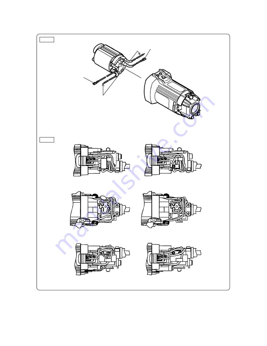
Fig. 5
Fig. 4
Connect to the
Brush Holder
[30]
(
Side A
)
Connect to the
Brush Holder
[30]
(
Side B
)
Side B
Side A
Connect both the internal wire of the Noise
Suppressor
[38]
and this wire to Tube (D)
[39]
with a solderless connection and connect it to the
Slide Switch
[35]
.
(If the Noise Suppressor
[38]
is not used,
connect this internal wire to the Slide Switch
[35]
after clamping Tube (D)
[39]
with the solderless
connection.)
(2) Connect the four internal wires of Stator (A)
[20]
with the parts indicated in Fig. 4.
Connect the internal wires correctly as shown in Fig. 5.
a. Choke coil and Noise Suppressor provided
b. Noise Suppressor not provided


