background image

OPERATION

--

--

 CONTROLS AND CONNECTIONS


15

Содержание DT3140

Страница 1: ...DT3140 User Manual 14 1 Super TFT Colour LCD Monitor ...

Страница 2: ...mark of Apple Computer Inc Other company and product names used herein are the property of their respective owners VESA is an acronym for Video Electronics Standards Association DPMS is an acronym for Display Power Management Signalling DDC is an acronym for Display Data Channel a VESA communication standard that allows monitors to support Plug Play on Windows 95 machines DDC 1 and DDC 2B refer to...

Страница 3: ...Connections n On Screen Display OSD Overview n On Screen Display OSD Adjustment n OtherFeatures TROUBLESHOOTING n ProblemChecklist HARDWARE TECHNICAL INFORMATION n Specifications H Video Signal Connections n VideoModes 9 9 11 12 15 16 18 28 29 31 32 33 Please read this manual thoroughly and keep it handy for reference Use the product only after reading and understanding the safety precautions desc...

Страница 4: ...le to predict and evaluate all circumstances beforehand Be alert and use your common sense l Do not perform any operation or action other than as described in this manual When in doubt call the designated field engineer l The hazard warnings which appear on the safety alert labels on the machine or in the manual have one of the following alert headings consisting of a hazard alert symbol and a sig...

Страница 5: ...nce staff of the incident A fire can occur if you continue using the product with foreign objects left inside A Warning Do not remove the cover Never attempt to remove the cover of the product There are high voltage parts inside which can cause an electric shock A Warning Do not try to modify or alter the product If you do so it could cause a fire electric shock and or malfunctioning A Warning Do ...

Страница 6: ...pecified power voltage Do not use any power source other than that indicated Failure to do so could cause a fire or electric shock A Warning Do not swallow liquid crystal In the event that the LCD panel is broken and liquid crystal flows out be careful not to inhale or swallow it Swallowing this substance can cause poisoning If it should enter your mouth rinse the mouth with water and then consult...

Страница 7: ... appropriate safety approved extension lead or consult your dealer Should it be necessary to change the mains plug this must be carried out by a competent person preferably a qualified electrician If there is no alternative to cutting off the mains plug ensure that you dispose of it immediately having first removed the fuse to avoid a possible shock hazard by inadvertent connection to the mains su...

Страница 8: ...eyestrain The eyes become fatigued if you keep watching the monitor for too long a period of time Take a break for five to ten minutes after each hour A Caution Be mindful of possible electromagnetic interference Electromagnetic interference is likely to occur if the product is used adjacent to other electronic equipment It can be the cause of noise and undesired degradation of electrical performa...

Страница 9: ...n WARNING LABELS The warning labels are located in the positions shown below Hazardous voltage Can cause death or severe injury Disconnect main power before servicing I I ...

Страница 10: ...INE CARE When the product is not in use keep the power cord unplugged and use a dust cover Occasionally use a soft dry cloth to clean the surface of the product For an extremely dirty spot or oil stain use a soft cloth thoroughly wrung out after being soaked in water or a neutral detergent to clean the soiled surface To remove dust use a dry cloth or an electric vacuum cleaner Avoid using thinner ...

Страница 11: ...JUST Press the A button to begin automatic adjustment The display may appear unclear or distorted while adjustment is in progress The word DONE will appear when adjustment is completed and the OSD window will return to the main menu If the image quality is not good try displaying a different application screen and repeat again from step 5 If this is still not successful you will need to make manua...

Страница 12: ...ails of the system unit power switch To remove the monitor s rear cover press both sides of the top edge of the cover and push down then pull the bottom edge towards you To replace it reverse these steps Monitor Monitor Rear cover Monitor cable Ensure correct orientation then push the plug onto the connector until it stops Turn the screws clockwise to fasten the connector Note This computer system...

Страница 13: ...tlet do it with your hand holding the plug Insert the power plug firmly until it stops l Use a proper safe power outlet or contact failure could occur l Do not use any power cord other than the one provided This monitor is ready for use immediately after setting up the computer system If you need to adjust the monitor in any way please refer to the OSD On Screen Display facility Please refer to yo...

Страница 14: ...OPERATION I W CONTROLS AND CONNECTIONS Power switch Power connector bottom view Tl SAVE LED orange BACK button I SELECT button A button 15 ...

Страница 15: ...o optimise the display use the on screen display OSD as described below The display size image position and brightness depend on the system hardware Make screen adjustments after carefully reading this manual If the screen cannot be adjusted as desired refer to your computer system manual to check if the display timing is consistent with that shown on page 33 The OSD feature supports the following...

Страница 16: ... computer refer to your computer s operation manual OSD BUTTONS The OSD uses a simple menu structure to access the functions You navigate within the menus using the buttons on the monitor front panel The buttons have the following actions l MENU button Toggles the OSD window on and off If settings have been changed the SAVE SETTINGS menu will appear before OSD terminates l A and v buttons These mo...

Страница 17: ...urrent display mode is not supported In this case the SAVE lamp will also blink After several seconds the display will switch off If the NOT SUPPORTED message appears your computer may be set to a video mode that is not supported by the D T3 14 0 Please be sure to select a supported mode at your computer Refer to Video Modes on page 33 If necessary refer to your computer s operation manual for inf...

Страница 18: ...rogress Please do not change your computer s display mode settings switch off the computer s power or disconnect the display cable while adjustment is in progress If automatic adjustment terminates unsuccessfully FAILED will be displayed If this occurs press the BACK button to return to the previous screen and then try automatic adjustment again If adjustment fails several times in succession try ...

Страница 19: ...fect results Some computers have unusual timing characteristics or other properties that make automatic adjustment difficult If automatic adjustment is not satisfactory you should proceed to manual adjustment H POSITION Adjusts the image position horizontally 20 ...

Страница 20: ...V POSITION Adjusts the image position vertically ...

Страница 21: ... screen that you are currently displaying Results may not always be perfect If the adjustment does not produce good results try changing to a different screen image or adjusting the contrast Please note that in some rare circumstances when a grey background made up of black and white dots is being displayed the image may display a pattern of lines Even adjusting the PHASE may not remove this and i...

Страница 22: ...lses per horizontal scan The default value varies according to the display mode You can adjust by up to 32 units above or below the default A poorly adjusted clock can produce wavy or striped images as illustrated below If you see this type of image adjust the clock until the image becomes normal Stripes Wavy image Lr Y 23 ...

Страница 23: ...CONTRAST Adjusts the contrast The factory default contrast value is 0 on a scale from 50 to 50 COLOR BALANCE Adjusts the colour balance Each colour value can be between 32 and 32 24 ...

Страница 24: ... the SAVE SETTINGS screen does not appear Note that the new settings are not saved if the OSD function closes automatically If you have enabled this feature be sure to save the new settings promptly This setting applies to all display modes OSD COLOUR Selects the OSD window colour from any one of 12 colours This setting applies to all display modes 25 ...

Страница 25: ...Note that this window automatically appears if you press the MENU button to terminate OSD adjustment Please do not switch off the power while saving is in progress otherwise the display may not operate correctly the next time you switch on CLEAR SETTINGS Restores user settings to the factory default values While the settings are being cleared CLEARING is displayed followed by DONE when complete No...

Страница 26: ...til the power is switched off and on again BRIGHTNESS Adjusts the brightness of the backlight The factory default brightness is 15 on a scale of 0 to 3 1 When the OSD is not active pressing the A or v buttons will cause the BRIGHTNESS Control Screen to appear You cannot reach this window from the OSD menus If you want to save the adjusted brightness value use SAVE SETTINGS see page 26 27 ...

Страница 27: ...vertical synchronisation signals are absent This is indicated by a bright SAVE LED located on the right side of the front panel Refer to your computer manual for VESA DPMS settings of the computer system unit PLUG PLAY The BT3140 supports DDC 1 and DDC 2B Data Display Channel 1 2B and is therefore compatible with Windows 95 Plug Play For more information about Plug Play refer to your system s user...

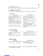
Страница 28: ...tch turned on Is the system in power saving mode 2 Discoloured picture Possible cause Is the monitor s signal cable properly connected Is the system unit set up correctly Check that the signal cable is firmly connected Turn the monitor s power switch on LED indicator lights green Touch the keyboard or mouse to return to normal mode Corrective action Check that the signal cable is firmly connected ...

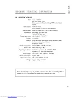
Страница 29: ...rlaced Direct l F cable with 15 pin D Sub connector Horizontal 1024 dots max Vertical 768 dots max 285 7x214 3 WxH 16 190 OOO OSD automatic adjustment display position phase clock contrast colour balance Brightness control VESA DPMS ENERGY STAR DDC 112B Plug Play Ambient temperature 10 35 C 50 95 F Humidity 20 80 non condensing 100 12OV I 200 240V AC 50 60Hz Approx 35W 375 x 199 x 327 W x D x H Ap...

Страница 30: ...he computer system unit 12 1 DDC D DDC data 13 HSYNC 14 VSYNC 15 DDC C Horizontal sync signal Vertical sync signal DDC clock output output output output Effective only on systems compliant with DDC 1 or DDC 2B Effective only on systems compliant with DDC 2B 32 ...

Страница 31: ...r reason use the monitor s OSD function to make the necessary adjustments When changing the display settings resolution numbers of colours etc please ensure that the chosen mode is one from the above If you select a non supported video mode the SAVE lamp will begin blinking after a few seconds and the screen may display NOT SUPPORTED although this may not be readable due to screen instability In t...

Страница 32: ...3 Fax 49 89 991 80 224 Email rplan hitachi eu com Hotline 49 180 551 25 51 12ct min Email HSE DUS Service Hitachi eu com HITACHI EUROPEAB HITACHI EUROPE SRL Box 77 Via T Gulli n 39 S 164 94 KISTA 20147 MILAN SWEDEN ITALY Tel 08 562 711 00 Tel 02 487861 Fax 08 562 711 11 Fax 02 48786381 Servizio Clienti Email csgswe hitachi eu com Tel 02 38073415 Email customerservice italy hitachi eu com HITACHI E...

Отзывы: