


46
1 ADJUSTMENT PROCEDURE START-UP
The P60X901 Plasma Display HDTV set pass through
adjustment procedures during
the
assembly process.
These adjustments must be done to assure the best
performance of the PDP set for the consumer.
Also, after servicing, these same adjustments must be
done. The adjustments are all made through the I
2
C bus
by changing data in the Adjustment mode menu.
1.1 HOW TO GET TO ADJUSTMENT MODE
Chassis adjustment
mode
can be
access by pressing
the R/C keys MENU + MENU + 8 + SELECT to enter
adjustment mode. For some parameters the only way
to see them is by selecting the parameter number
than
press SELECT in order to see it; then DATA can be
change if other parameter needs to change then press
key then repeat the same procedure
.
key on
Front panel or EXIT key of R/C to exit
service adjustment mode.
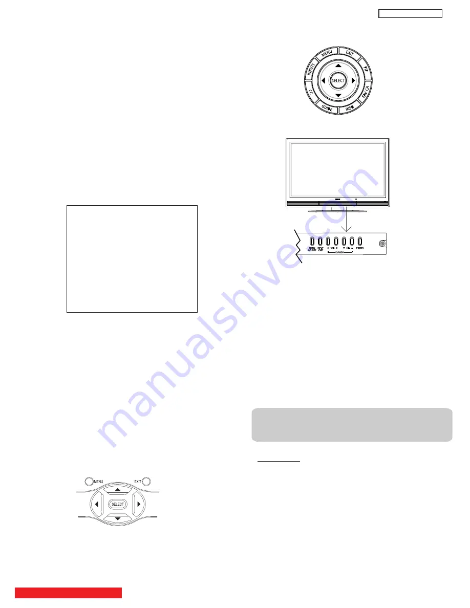
1.2 CHANGING DATA AND SELECTING ADJUSTMENT
CODE
When the PDP set is in adjustment mode, the cursor
,
,
,
and MENU keys of the remote control or front panel
may be used as the adjustment keys.
(1)
Use any Hitachi remote control when making an
adjustment.
,
keys are used for selecting adjustment
item
.
,
keys are used for changing data values.
MENU key is used to advance through the adjustment
mode menus and pages.
ADJUST MODE
FACT RESET
MEMORY INIT
RGB
WHITE BAL HIGH
WHITE BAL MED
WHITE BAL STD
WHITE BAL B/W
(2)
To make a selection, use the
NUMBER pad
on the
PDP
R
/
C
; example : select
DEVICE
press 69 then SELECT
the DATA shown is "EB" ; if this DATA needs to be change
press the keys to modify, when finish press SELECT
key to store the new DATA value.
normal condition.
(3)
After finishing the necessary adjustment press the R/C
EXIT key or EXIT key on the front panel.
Adjustment mode is released and PDP set returns to
normal condition.
,
,
2 MEMORY INITIALIZE
2.1 MEMORY INITIALIZE OPERATION
NOTE:
The execution of this function returns the
adjustment codes to the preset values, therefore,
adjustment data will be lost
.
Procedure
(1) Enter Adjustment mode by the method described in
sub-items 1.1 and 1.2 from item 1 (“Adjustment
procedure start up”).
(2) Get to the second page of Adjust Mode by pressing
remote control “Menu” key once, or with either the
R/C or front panel
,
cursor keys several times.
(3) Select MEMORY INIT adjust code.
(4) Activate MEMORY INIT by pressing
cursor key for
more than 3 seconds.
(5) Check the following process for initialization opera-
tion.
BACK TO ADJUSTMENTS
DW
3
U
To escape from Adjustment Mode press “INPUT”
Содержание Director's P60X901
Страница 66: ...DW3U 65 FINAL WIRING DIAGRAM TABLE OF CONTENTS ...
Страница 70: ...QUICK DISASSEMBLE GUIDE BACK COVER 1 69 DW3U Remove Screw M3M 6 20 8 pcs Handles Remove Screw M3M 6 12 2 pcs ...
Страница 71: ...QUICK DISASSEMBLE GUIDE BACK COVER 2 70 DW3U Remove Screw M3D 4 10 32 pcs Remove Back Cover P QA03684K ...
Страница 79: ...QUICK DISASSEMBLE GUIDE FRAME REMOVAL STEP 7 78 DW3U Remove Screw M3S 4 16 4 pcs Bottom Bezel Ass y ...
Страница 82: ...FINAL ASSEMBLY GUIDE TABLE OF CONTENTS 81 DW3U ...
Страница 83: ...FINAL ASSEMBLY GUIDE 82 DW3U ...
Страница 84: ...FINAL ASSEMBLY GUIDE 83 DW3U ...
Страница 85: ...FINAL ASSEMBLY GUIDE 84 DW3U ...
Страница 86: ...FINAL ASSEMBLY GUIDE 85 DW3U ...
Страница 87: ...FINAL ASSEMBLY GUIDE 86 DW3U ...
Страница 88: ...FINAL ASSEMBLY GUIDE 87 DW3U ...
Страница 89: ...FINAL ASSEMBLY GUIDE 88 DW3U ...
Страница 90: ...FINAL ASSEMBLY GUIDE 89 DW3U ...
Страница 91: ...FINAL ASSEMBLY GUIDE 90 DW3U ...
Страница 92: ...FINAL ASSEMBLY GUIDE 91 DW3U ...
Страница 93: ...FINAL ASSEMBLY GUIDE 92 DW3U ...
Страница 94: ...FINAL ASSEMBLY GUIDE 93 DW3U ...
Страница 95: ...FINAL ASSEMBLY GUIDE 94 DW3U ...
Страница 96: ...FINAL ASSEMBLY GUIDE 95 DW3U ...
Страница 97: ...FINAL ASSEMBLY GUIDE 96 DW3U ...
Страница 112: ...BACK TO TABLE OF CONTENTS 111 PRINTED CIRCUIT BOARDS DW3 U TERMINAL PWB Component side DW3 U ...
Страница 113: ...PRINTED CIRCUIT BOARDS DW3 U TERMINAL PWB Solder side DW3 U 112 ...
Страница 114: ...PRINTED CIRCUIT BOARDS DW3 SD CARD PWB Included on Terminal PWB Ass y DW3 U 113 Component side ...
Страница 115: ...PRINTED CIRCUIT BOARDS DW3 SD CARD PWB Included on Terminal PWB Ass y DW3 U 114 Solder side ...
Страница 117: ...PRINTED CIRCUIT BOARDS DW3 U FILTER PWB Component side DW3 U 116 Component side ...
Страница 118: ...PRINTED CIRCUIT BOARDS DW3 U FILTER PWB Solder side DW3 U 117 Solder side ...
Страница 121: ...PRINTED CIRCUIT BOARDS DW3 U POD PWB DW3 U 120 Component side ...
Страница 122: ...PRINTED CIRCUIT BOARDS DW3 U POD PWB DW3 U 121 Solder side ...
Страница 123: ...PRINTED CIRCUIT BOARDS DW3 U SWITCH PWB DW3 U 122 Component side Solder side ...
Страница 143: ......


