-14-
Reassembly can be accomplished by following the disassembly procedure in reverse. However, special
attention should be given to the following items.
1. Reassembly of the hammering mechanism and the vibration reduction mechanism
(a)
First Gear
[116]
and Crank Shaft
[79]
Press-fit the Oil Seal
[84]
into the Crank Case
[115]
and
mount O-ring (B)
[83]
. Press-fit the Ball Bearing
6204DDCMPS2L
[82]
. Mount the Retaining Ring for D47
Hole
[81]
using a retaining ring puller. Press-fit the
Crank Shaft
[79]
into the Ball Bearing 6204DDCMPS2L
[82]
. Put the Feather Key 3 x 3 x 25
[80]
in the groove of
the Crank Shaft
[79]
and press-fit the First Gear
[116]
with a suitable jig while holding the flat portion of the
Crank Shaft
[79]
with a steel bar. Before press-fitting,
make sure that the Feather Key 3 x 3 x 25
[80]
fits in the
key groove of the First Gear
[116]
. Press-fit the Second
Pinion
[117]
until it contacts the First Gear
[116]
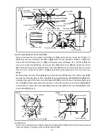
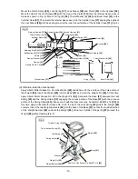
(Fig. 6).
(b)
Piston
[35]
Insert the Connecting Rod
[36]
into the Piston
[35]
and insert the Piston Pin
[34]
into the 10-mm dia. hole
(marked side) of the Piston
[35]
. (Be careful not to protrude the Piston Pin
[34]
from the outside diameter
of the Piston
[35]
.) Mount the O-ring
[32]
to the Piston
[35]
to make the piston ass'y. Move the crank pin
of the Crank Shaft
[79]
to the bottom dead center and mount the piston ass'y to the Crank Shaft
[79]
from
the Cylinder Case
[37]
side of the Crank Case
[115]
. Mount the Retaining Ring for D12 Shaft
[78]
using a
retaining ring puller (Fig. 7).
(c)
Cylinder
[26]
and Retainer Sleeve
[19]
Mount the Retainer Damper
[17]
, Thrust Washer (A)
[16]
and Sleeve
[15]
(with the Ball Bearing 6008CM
[14]
press-fitted) to the Retainer Sleeve
[19]
in this order and fix it with the Retaining Ring D40
[13]
.
Mount the Second Hammer
[21]
(with the O-ring
[20]
mounted), Damper Washer
[22]
, Damper
[23]
and
Damper Holder
[24]
to the Retainer Sleeve
[19]
in this order aligning the rounded portion of the Damper
Washer
[22]
with the rounded portion of the Second Hammer
[21]
. Insert the Striker
[31]
(with the O-ring
[32]
mounted) into the Cylinder
[26]
then insert the Cylinder
[26]
into the Retainer Sleeve
[19]
. Secure
the Retainer Sleeve
[19]
and the Cylinder
[26]
by inserting the eight Needle Pins D8 x 6
[25]
into the 8-
mm dia. holes and cover it with Spring Holder (B)
[29]
.
First Gear
[116]
BB.6204DDCMPS2L
[82]
Support
Oil Seal
[84]
Reassembly
Fig. 6
Piston Pin
[34]
Connecting Rod
[36]
Piston
[35]
O-ring
[32]
Piston ass’y
Crank Shaft
[79]
Retaining Ring for D12 Shaft
[78]
Crank Case
[115]
Mark
Fig. 7

