--- 14 ---
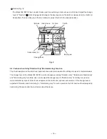
Striker
Second
hammer
Cylinder
Grip
Front cap
Armature
Bevel pinion
Second gear
Clutch
Air
chamber
Steel ball
Needle pin
Key rail
Piston
O-ring
Connecting rod
Crank shaft
First gear
Bevel
gear
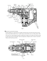
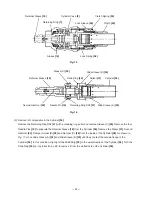
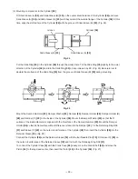
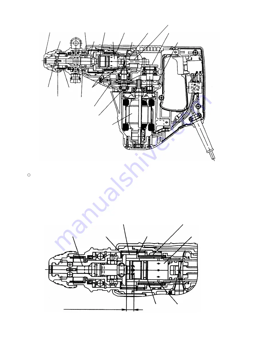
Fig. 3
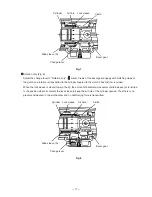
Mechanism to prevent idle hammering
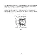
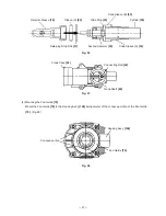
When the working tool is released from the workpiece, slide sleeve (A) and the second hammer are forcibly
moved to the position illustrated in Fig. 4 by clutch spring, and the striker moves out of striking position. When
this occurs, the air holes located at the position unaffected by the rebound of the striker at no load are opened
and the pressure within the air chamber remains unchanged even though the piston continues to reciprocate,
thereby preventing striking operation.
Fig. 4
Retainer
sleeve
Striker
Slide sleeve (A)
Second hammer
Moving distance of second
hammer and striker
Clutch spring
Air chamber
Air hole
Slide sleeve (B)
Slide ring


