background image

4

English


A moment of inattention while operating power 

tools may result in serious personal injury.

b)  Use personal protective equipment. Always 

wear eye protection.


Protective equipment such as dust mask, 

non-skid safety shoes, hard hat, or hearing 

protection used for appropriate conditions will 

reduce personal injuries.

c)  Prevent unintentional starting. Ensure the 

switch is in the o

 -position before connecting 

to power source and/or battery pack, picking 

up or carrying the tool.


Carrying power tools with your finger on the 

switch or energising power tools that have the 

switch on invites accidents.

d)  Remove any adjusting key or wrench before 

turning the power tool on. 


A wrench or a key left attached to a rotating part 

of the power tool may result in personal injury.

e)  Do not overreach. Keep proper footing and 

balance at all times.


This enables better control of the power tool in 

unexpected situations.

f)  Dress properly. Do not wear loose clothing 

or jewellery. Keep your hair, clothing and 

gloves away from moving parts.


Loose clothes, jewellery or long hair can be 

caught in moving parts.

g)  If devices are provided for the connection 

of dust extraction and collection facilities, 

ensure these are connected and properly 

used.


Use of dust collection can reduce dust-related 

hazards.

4)    Power tool use and care

a)  Do not force the power tool. Use the correct 

power tool for your application. 


The correct power tool will do the job better and 

safer at the rate for which it was designed.

b)  Do not use the power tool if the switch does 

not turn it on and o

 .


Any power tool that cannot be controlled with 

the switch is dangerous and must be repaired.

c)  Disconnect the plug from the power source 

and/or the battery pack from the power tool 

before making any adjustments, changing 

accessories, or storing power tools. 


Such preventive safety measures reduce the 

risk of starting the power tool accidentally.

d)  Store idle power tools out of the reach of 

children and do not allow persons unfamiliar 

with the power tool or these instructions to 

operate the power tool.


Power tools are dangerous in the hands of 

untrained users.

e)  Maintain power tools. Check for misalignment 

or binding of moving parts, breakage of parts 

and any other condition that may a

 ect the 

power tool’s operation.


If damaged, have the power tool repaired 

before use.


Many accidents are caused by poorly maintained 

power tools.

f)  Keep cutting tools sharp and clean.


Properly maintained cutting tools with sharp 

cutting edges are less likely to bind and are 

easier to control.

g)  Use the power tool, accessories and tool bits 

etc. in accordance with these instructions, 

taking into account the working conditions 

and the work to be performed.


Use of the power tool for operations different 

from those intended could result in a hazardous 

situation.

5)  Service

a)  Have your power tool serviced by a quali

fi

 ed 

repair person using only identical replacement 

parts.


This will ensure that the safety of the power tool 

is maintained.

SPECIFIC SAFETY RULES AND SYMBOLS
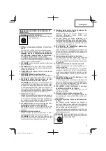
1.  Wear ear protectors.

Exposure to noise can cause hearing 

loss.

2.  Use auxiliary handles, if supplied with the tool.

  Loss of control can cause personal injury.

3.  Hold power tools by insulated gripping surfaces 

when performing an operation where the cutting 

tool may contact hidden wiring or its own cord.

  Cutting accessory contacting a “live” wire may make 

exposed metal parts of the power tool “live” and could 

give the operator an electric shock. 

4. NEVER

 touch the tool bit with bare hands after 

operation.

5. NEVER

 wear gloves made from materials likely to roll 

up such as cotton, wool, cloth or string, etc.

6. ALWAYS

 attach the side handle and securely grip the 

Rotary Hammer.

7.  NEVER touch moving parts.


NEVER 

place your hands, 

fi

 ngers or other body parts 

near the tool’s moving parts.

8.  Never operate without all guards in place.


NEVER 

operate this tool without all guards or safety 

features in place and in proper working order. If 

maintenance or servicing requires the removal of a 

guard or safety feature, be sure to replace the guard or 

safety feature before resuming operation of the tool.

000Book̲DH26PC̲NA.indb   4

000Book̲DH26PC̲NA.indb   4

2016/01/25   14:08:42

2016/01/25   14:08:42

Содержание DH 26PF

Страница 1: ...uses blessures corporelles Ce mode d emploi contient d importantes informations à propos de la sécurité de ce produit Prière de lire et de comprendre ce mode d emploi avant d utiliser l outil motorisé Garder ce mode d emploi à la disponibilité des autres utilisateurs avant qu ils utilisent l outil motorisé MANUAL DE INSTRUCCIONES E INSTRUCCIONES DE SEGURIDAD ADVERTENCIA La utilización inapropiada ...

Страница 2: ...EMENT PLUS SUR 20 DESCRIPTION FONCTIONNELLE 21 NOM DES PARTIES 21 SPECIFICATIONS 22 ASSEMBLAGE ET FONCTIONNEMENT 22 APPLICATIONS 22 AVANT L UTILISATION 22 UTILISATION 23 COMMENT UTILISER LA COURONNE POUR UNE CHARGE LEGERE 26 ENTRETIEN ET INSPECTION 28 ACCESSOIRES 29 ACCESSOIRES STANDARD 29 ACCESSOIRES SUR OPTION 29 LISTA DES PIÈCES 49 INFORMACIÓN IMPORTANTE SOBRE SEGURIDAD 33 SIGNIFICADO DE LAS PA...

Страница 3: ... cordless power tool 1 Work area safety a Keep work area clean and well lit Cluttered or dark areas invite accidents b Do not operate power tools in explosive atmospheres such as in the presence of flammable liquids gases or dust Power tools create sparks which may ignite the dust or fumes c Keep children and bystanders away while operating a power tool Distractions can cause you to lose control 2...

Страница 4: ... the power tool or these instructions to operate the power tool Power tools are dangerous in the hands of untrained users e Maintain power tools Check for misalignment or binding of moving parts breakage of parts and any other condition that may affect the power tool s operation If damaged have the power tool repaired before use Many accidents are caused by poorly maintained power tools f Keep cutt...

Страница 5: ...top 19 Carefully handle power tools Should a power tool be dropped or struck against hard materials inadvertently it may be deformed cracked or damaged 20 Do not wipe plastic parts with solvent Solvents such as gasoline thinner benzine carbon tetrachloride and alcohol may damage and crack plastic parts Do not wipe them with such solvents Wipe plastic parts with a soft cloth lightly dampened with s...

Страница 6: ...6 English SAVETHESE INSTRUCTIONS AND MAKETHEM AVAILABLETO OTHER USERS AND OWNERS OFTHISTOOL 000Book DH26PC NA indb 6 000Book DH26PC NA indb 6 2016 01 25 14 08 43 2016 01 25 14 08 43 ...

Страница 7: ...trations in this Instruction Manual may show details or attachments that differ from those on your own power tool NAME OF PARTS DH26PC DH26PF DH28PFY Housing Housing Nameplate Nameplate Drill bit Drill bit Front cap Front cap Grip Grip Depth gauge Depth gauge Side handle Side handle Push button Push button Switch trigger Switch trigger Change lever Change lever Push button Push button Stopper Stopp...

Страница 8: ...in the ON position the power tool will start operating immediately and can cause serious injury 3 Extension cord Whentheworkareaisfarawayfromthepowersource useanextensioncordofsufficientthicknessandrated capacity The extension cord should be kept as short as practicable WARNING Damaged cord must be replaced or repaired 4 Check the receptacle If the receptacle only loosely accepts the plug the recept...

Страница 9: ...ector B by attaching to drill bits which have 6 17 32 166 mm 6 19 64 160 mm and 4 21 64 110 mm overall length Dumpparticlesaftereverytwoorthreeholeswhen drilling Please replace the drill bit after removing dust collector B 8 Selecting the driver bit Screw heads or bits will be damaged unless a bit appropriateforthescrewdiameterisemployedtodrive in the screws 9 Confirm the direction of bit rotation...

Страница 10: ...uck to the chuck adaptor 2 The part of the SDS plus shank is the same as the drill bit Therefore refertotheitemof Mountingthedrillbit for attaching it CAUTION Application of force more than necessary will not only reducing drilling efficiency at all but will deteriorate the tip edge of the drill bit and reduce the service life of the rotary hammer in addition Drill bit may snap off while withdrawing ...

Страница 11: ...eration Shouldtheholebeexcessively small or shallow requiring much power to drive thescrewintoit thethreadofthewoodscrewmay sometimes be damaged 6 Hammering only Thisrotaryhammercanbesettohammeringonlymode by pressing the push button and turning the change lever to mark Fig 12 Change lever Push button Fig 12 1 Mount the bull point cold chisel or other tool bit 2 Press the push button and set the c...

Страница 12: ...the center pin into the guide plate until it stops 4 Engage the guide plate with the core bit and turn the guide plate to left or right so that it does not fall even if it faces downward Fig 20 Guide plate Center pin Core bit Core bit tip Fig 20 2 How to bore Fig 21 1 Connect the plug to the receptacle 2 A spring is installed in the center pin Push it lightly to thewallorthefloorstraight Connectal...

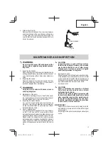
Страница 13: ...atest technological advancements Accordingly somepartsmaybechangedwithoutprior notice WARNING Be sure to switch power OFF and disconnect the plug from the receptacle during maintenance and inspection 1 Inspecting the drill bits Sinceuseofadulltoolwillcausemotormalfunctioning anddegradedefficiency replacethedrillbitwithanew one or resharpening without delay when abrasion is noted 2 Inspecting the scr...

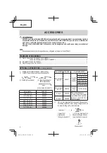
Страница 14: ...when using a straight shank bit for impact drilling with a rotary hammer 1 2 13 mm Hammer Drill Chuck SDS plus shank includes Chuck wrench Chuck wrench Impact Drill Application Straight shank Bit ACCESSORIES WARNING ALWAYS use Only authorized HITACHI replacement parts and accessories Never use replacement parts or accessories which are not intended for use with this tool Contact HITACHI if you are...

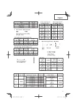
Страница 15: ...4 W5 16 8 mm 971795 W3 8 9 5 mm 971796 W1 2 12 7 mm 971797 W5 8 15 9 mm 971798 Inner wedge type with the headless screw Anchor size Code No W1 4 6 3 mm 971799 W5 16 8 mm 971800 W3 8 9 5 mm 971801 W1 2 12 7 mm 971802 W5 8 15 9 mm 971803 3 Large hole boring Rotation Hammering Guide Plate Center pin Core Bit Core bit Shank SDS plus shank Guide plate Core bit outer diameter Code No Core bit outer diam...

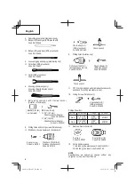
Страница 16: ...ck wrench Code No 321814 Chuck adaptor G SDS plus shank Code No 303623 Chuck wrench 9 Drilling holes Rotation only Drill chuck 13VLD D includes chuck wrench Code No 321813 Chuck adaptor D SDS plus shank Code No 303624 Chuck wrench 1 2 13mm drillchuckass y includeschuckwrench and chuck for drilling into steel or wood 10 Driving Screws Rotation only Bit No Chuck adaptor D SDS plus shank Code No 3036...

Страница 17: ...rcesavertissementsetinstructionspeutengendrerdeschocsélectriques desincendies et ou des blessures graves Conservez tous les avertissements et toutes les instructions pour vous y référer ultérieurement Le terme outil électrique utilisé dans les avertissements se réfère aux outils électriques câblé ou aux outils à piles sans fil 1 Sécurité de l aire de travail a Maintenir l aire de travail propre et...

Страница 18: ... cas de dispositifs destinés au raccordement d installations d extraction et de recueil de la poussière veiller à ce qu ils soient correctement raccordés et utilisés L utilisation d un dispositif de collecte de la poussière peut réduire les dangers associés à la poussière 4 Utilisation et entretien d un outil électrique a Ne pas forcer sur l outil électrique Utiliser l outil électrique adapté à vo...

Страница 19: ...n personnel non autorisé 12 Maintenir toutes les vis tous les boulons et les couvercles fermement en place Maintenir toutes les vis tous les boulons et les couvercles fermement montés Vérifier leurs conditions périodiquement 13 Ne pas utiliser les outils motorisés si le revêtement de plastique ou la poignée est fendu Des fentes dans le revêtement ou la poignée peuvent entraîner une électrocution D...

Страница 20: ...ur C est pourquoi le symbole ou les mots Double insulation double isolation apparaissent sur l outil motorisé ou sur la plaque signalétique Bien que ce système n ait pas de mise à terre extérieure il est quand même nécessaire de suivre les précautions de sécurité électrique données dans ce mode d emploi y compris de ne pas utiliser l outil motorisé dans un environnement humide Pour garder le systè...

Страница 21: ...peuvent montrer des détails ou des accessoires différents de ceux de l outil motorisé utilisé NOM DES PARTIES DH26PC DH26PF DH28PFY Carter Carter Plaque signalétique Plaque signalétique Foret de perçage Foret de perçage Capuchon avant Capuchon avant Attache coulissante Attache coulissante Jauge de profondeur Jauge de profondeur Poignée laterale Poignée laterale Bouton poussoir Bouton poussoir Décle...

Страница 22: ...ues et de vis à bois avec accessoires en option Fonction percussion seulement Burinage léger du béton creusage de rainures et cassure d angles AVANT L UTILISATION 1 Source d alimentation S assurer que la source d alimentation qui doit être utiliséeestconformeàlasourced alimentationrequise spécifiée sur la plaque signalétique du produit 2 Interrupteur d alimentation S assurer que l interrupteur est...

Страница 23: ...acile Lors de la mise sous tension du marteau rotatif alors le collecteur à poussière B est détaché de la surface en béton le collecteur à poussière B va tourner en même temps que le foret Ne bien activer l interrupteur de mise sous tension qu après avoir appuyé le collecteur à poussière B sur la surface en béton Si le collecteur à poussière B est utilisé avec un foret de plus de 7 15 32 190 mm de...

Страница 24: ...ret de perçage touche une poutre en fer la mèche s arrête immédiatement et la perceuseréagitentournant Parconséquent tenir fermement la poignée principale et la poignée latérale comme indiqué à la Fig 8 3 Rotation seulement Cetteperceuseàpercussionpeutêtremisesurlemode de rotation uniquement en appuyant sur le bouton poussoir et en tournant le sélecteur vers le repère Fig 9 Sélecteur Bouton pousso...

Страница 25: ...e étantdonnéquelamècheglissesouventdelatêtedes vis ordinaires 2 Enfoncement de vis à bois Avant d enfoncer des vis à bois préparez d abord des trous appropriés aux vis utilisées dans le bois Appliquez la mèche aux fentes de la tête de la vis et enfoncez la vis dans le bois en douceur Après avoir fait tourner le marteau rotatif à petite vitesse pendant un moment jusqu à ce que la vis à bois soit pa...

Страница 26: ...econique Fig 16 4 Pour retirer la mèche queue conique introduire la clavette dans la fente du raccord de queue conique et frapper la tête de la clavette avec un marteau alors que le perceuse est placée sur le support Fig 17 Raccord de queue conique Support Clavette Fig 17 COMMENT UTILISER LA COURONNE POUR UNE CHARGE LEGERE Utiliser la couronne pour percer de grands trous L utiliser avec le goujon ...

Страница 27: ...u trou est déterminée Continuer à percer après avoir retiré le goujon central et la plaque de guidage de la couronne 4 Si l on applique une force excessive cela donnera un travail bâclé et abîmera la pointe du foret de perçage réduisant ainsi la durée de service du marteau rotatif Fig 21 PRECAUTION Quand on retire le goujon central et la plaque de guidage mettre l interrupteur sur la position d ar...

Страница 28: ...n de l efficacité remplacez la mèche usée par une neuve ou aiguisez la immédiatement et dès que vous notez une certaine usure 2 Inspection des vis Inspecter régulièrement toutes les vis pour s assurer qu elles sont bien serrées Si l une des vis était desserrée la resserrer immédiatement AVERTISSEMENT Utiliser la marteau rotatif avec des vis desserrées est extrêmement dangereux 3 Entretien du moteur ...

Страница 29: ...Perçage de trous d ancrage Rotation percussion Foretdeperçage Queueconique etraccorddequeue conique 1 Foret de perçage Queue conique 2 Raccord de queue conique Tige SDS plus Clavette No de code 944477 Dia externe No de code 7 16 11 mm 944460 1 2 12 3 mm 944461 1 2 12 7 mm 993038 9 16 14 3 mm 944462 9 16 14 5 mm 944500 11 16 17 5 mm 944463 7 8 21 5 mm 944464 Tupe de cône No de code Foret de perçage...

Страница 30: ...totale 10 1 4 260 mm 10 1 4 260 mm 6 1 4 160 mm 10 1 4 260 mm No de code 302979 302978 303622 302977 Raccord de mise en place de la fixation pour marteau Type à cale extérieure avec vis femelle Dimension de l ancrage No de code W1 4 6 3 mm 971794 W5 16 8 mm 971795 W3 8 9 5 mm 971796 W1 2 12 7 mm 971797 W5 8 15 9 mm 971798 Type à cale intérieure avec vis sans tête Dimension de l ancrage No de code ...

Страница 31: ...n porte foret raccord G de mandrin vis spéciale et clé de mandrin Vis spéciale No de code 981122 Mandrin porte foret 13VLRB D y compris la clé de mandrin No de code 321814 Raccord G de mandrin Tige SDS plus No de code 303623 Clé de mandrin 9 Perçage de trous Rotation seulement Mandrin porte foret 13VLD D y compris la clé de mandrin No de code 321813 Raccord D de mandrin Tige SDS Plus No de code 30...

Страница 32: ...2 25 mm 971512Z 11 Capuchon anti poussière Collecteur à poussière B Capuchon anti poussière No de code 971787 Collecteur à poussière B No de code 306885 12 Graisse pour marteau rotatif 1 1lbs 500g enboîteplastique No decode335781 0 13 lbs 60 g en tube No de code 335782 REMARQUE Les spécifications sont sujettes à modification sans aucune obligation de la part de HITACHI 000Book DH26PC NA indb 32 00...

Страница 33: ...ctrica un incendio y o daños graves Guarde todas las advertencias e instrucciones para futura referencia El término herramienta eléctrica en las advertencias hace referencia a la herramienta eléctrica que funciona con la red de suministro con cable o a la herramienta eléctrica que funciona con pilas sin cable 1 Seguridad en el área de trabajo a Mantenga la zona de trabajo limpia y bien iluminada L...

Страница 34: ...un sistema de recogida de polvo puede reducir los riesgos relacionados con el polvo 4 Utilización y mantenimiento de las herramientas eléctricas a No fuerce la herramienta eléctrica Utilice la herramienta eléctrica correcta para su aplicación La herramienta eléctrica correcta trabajará mejor y de forma más segura si se utiliza a la velocidad para la que fue diseñada b No utilice la herramienta elé...

Страница 35: ...12 Mantenga todos los tornillos pernos y cubiertas firmemente fijados en su lugar Mantenga todos los tornillos pernos y cubiertas firmemente montados Compruebe periódicamente su condición 13 No utilice herramientas eléctricas si la carcasa o la empuñadura de plástico está rajada Las rajas en la carcasa o en la empuñadura de plástico pueden conducir a descargas eléctricas Tales herramientas no debe...

Страница 36: ...s conectados a la fuente de alimentación del bastidor exterior manejado por el operador Por lo tanto en la herramienta eléctrica o en su placa de características aparecen el símbolo o las palabras Double insulation aislamiento doble Aunque este sistema no posee puesta a tierra externa usted deberá seguir las precauciones sobre seguridad eléctrica ofrecidas en este Manual de instrucciones incluyend...

Страница 37: ...en mostrar detalles o accesorios diferentes a los de la propia herramienta eléctrica NOMENCLATURA DH26PC DH26PF DH28PFY Carcase Carcase Placa de características Placa de características Broca Broca Cubierta frontal Cubierta frontal Sujetador Sujetador Calibre de profundidad Calibre de profundidad Mango lateral Mango lateral Botón de empuje Botón de empuje Conmutador de gatillo Conmutador de gatill...

Страница 38: ...omacorriente Si el enchufe del cable de alimentación queda flojo en el tomacorriente habrá que reparar éste Póngase en contactoconunelectricistacualificadoparaquerealice las reparaciones adecuadas Si utilizase un tomacorriente en este estado podría producirserecalentamiento loquesupondríaunriesgo serio 5 Confirme las condiciones del medio ambiente Condirmequeellugardetrabajoestéenlascondiciones ap...

Страница 39: ...a apropiada según sea el diámetro del tornillo 9 Confirmar la dirección de rotación de la broca Fig 6 Labrocarotahacialaderecha mirándoladesdeatrás al oprimir el lado R del botón de empuje Para hacer girar la broca hacia la izquierda se oprime el lado L del botón de empuje Fig 6 Botón de empuje Broca PartedelSDS más vástago Cubierta frontal Sujetador Fig 2 3 Verifiquesiestabienaseguradotirandodela...

Страница 40: ... golpeteo presionando el pulsador y girando la palanca selectora hasta la marca Fig 7 Botón de empuje Palanquita selectora Fig 7 1 Montar la broca 2 Presionar el interruptor de gatillo después de poner la punta de la broca en la posición para taladrar Fig 8 Fig 8 3 Noesnecesariopresionarconfuerzalabroca Presionar ligeramente la broca de forma que el polvo producido al taladrar salga al exterior gr...

Страница 41: ...learlaperforadoradepercusiónen la función de rotación y golpeteo con el adaptador de portabroca D y la broca instalados 5 Atornillando tornillos para madera Fig 11 1 Escogerunabrocadestornilladorapropiadayemplear tornillos con cabeza en lo posible debido a que los tornillos con cabeza hacen que se zafe fácilmente el destornillador 2 Atornillado Antes de atornillar los tornillos para madera hay que...

Страница 42: ...ificada Sujetador Cubierta frontal Broca Adaptador de la espiga ahusada Fig 16 4 Para quitar la broca espiga ahusada insertar la chaveta en la ranura del adaptador de la espiga ahusada y golpear la cabeza de la chaveta con un martillo Usar apoyos como se muestra en la Fig 17 Adaptador de la espiga ahusada Apoyo Chaveta Fig 17 MODO DE USAR LA BARRENA TUBULAR PARA CARGAS LIGERAS Cuando se tengan que...

Страница 43: ... 3 Al taladrar aproximadamente 3 16 5 mm en profundidad la posición del agujero queda ya establecida Quitar el pasador central y la placa guía de la barrena tubular y seguir taladrando 4 La aplicación de una fuerza excesiva acelerará el cumplimiento del trabajo pero deteriorará la punta de labrocareduciendoladuracióndelmartilloperforador Fig 21 PRECAUCIÓN Cuandosequiteelpasadorcentralylaplacaguía ...

Страница 44: ... del taladro hay que reemplazar las brocas en malascondicionespornuevasoafilarlasdeinmediato al advertir abrasión 2 Inspección de los tornillos Inspeccione regularmente todos los tornillos y asegúrese de que estén bien apretados Si hay algún tornillo flojo apriételo inmediatamente ADVERTENCIA La utilización de esta martillo perforador con tornillos flojos es extremadamente peligroso 3 Mantenimient...

Страница 45: ...abrocas del martillo perforador de 1 2 13 mm Para la operación de taladrado cuando emplee una broca de vástago recto para taladrar con un martillo giratorio ACCESORIOS ADVERTENCIA UTILICE únicamente repuestos y accesorios autorizados por HITACHI No utilice nunca repuestos o accesorios no previstos para usar con esta herramienta Si tiene dudas en cuanto a la seguridad de usar determinado repuesto o...

Страница 46: ...d total 10 1 4 260 mm 10 1 4 260 mm 6 1 4 160 mm 10 1 4 260 mm Núm de código 302979 302978 303622 302977 Adaptador de montaje de ancla para martillo manual Tipo de reborde exterior con tornillo hembra Medida de ancla Núm de código W1 4 6 3 mm 971794 W5 16 8 mm 971795 W3 8 9 5 mm 971796 W1 2 12 7 mm 971797 W5 8 15 9 mm 971798 Tipo de reborde interior con tornillo sin cabeza Medida de ancla Núm de c...

Страница 47: ...de colocación de pernos para anclaje químico Rotación golpeteo SDS plus vástago Adaptador de anclaje químico de 1 2 12 7 mm Núm de código 303044 Adaptador de anclaje químico de 3 4 19 mm Núm de código 303045 Manguito adaptador a la venta el mercado 8 Perforación Rotación solamente Portabrocas adaptador G del portabrocas tornillo especál y llave de portabrocas Tornillo especial Núm de código 981122...

Страница 48: ...1 4 5 16 6 8 mm 31 32 25 mm 971512Z 11 Copa de polvo Colector de polvo B Copa de polvo Núm de código 971787 Colector de polvo B Núm de código 306885 12 Grasa para martillo perforador 1 1 libras 500 g en caja plástica Núm de código 335781 0 13 libras 60 g en tubo Núm de código 335782 NOTA Las especificaciones están sujetas a cambio sin ninguna obligación por parte de HITACHI 000Book DH26PC NA indb ...

Страница 49: ...ER RING 1 35 STRIKER 1 36 O RING D17 1 37 PISTON 1 38 PISTON PIN 1 39 BEARING WASHER 1 40 PISTON WASHER 2 41 PINION SLEEVE A 1 42 LOCK PLATE 1 43 SECOND PINION 1 44 CLUTCH SPRING 1 45 CLUTCH 1 46 WASHER 1 ITEM NO PART NAME Q TY 47 SECOND SHAFT 1 48 RECIPROCATING BEARING 1 49 SEAL LOCK HEX SOCKET HD BOLT M5 16 2 50 BEARING HOLDER 1 51 BEARING COVER 1 52 FIRST GEAR 1 53 O RING D72 2 1 54 INNER COVER...

Страница 50: ...ER RING 1 35 STRIKER 1 36 O RING D17 1 37 PISTON 1 38 PISTON PIN 1 39 BEARING WASHER 1 40 PISTON WASHER 2 41 PINION SLEEVE A 1 42 LOCK PLATE 1 43 SECOND PINION 1 44 CLUTCH SPRING 1 45 CLUTCH 1 46 WASHER 1 ITEM NO PART NAME Q TY 47 SECOND SHAFT 1 48 RECIPROCATING BEARING 1 49 SEAL LOCK HEX SOCKET HD BOLT M5 16 2 50 BEARING HOLDER 1 51 BEARING COVER 1 52 FIRST GEAR 1 53 O RING D72 2 1 54 INNER COVER...

Страница 51: ... WASHER 2 41 PINION SLEEVE A 1 42 LOCK PLATE 1 43 SECOND PINION 1 44 CLUTCH SPRING 1 45 CLUTCH 1 46 WASHER 1 47 SECOND SHAFT 1 48 RECIPROCATING BEARING 1 49 SEAL LOCK HEX SOCKET HD BOLT M5 16 2 ITEM NO PART NAME Q TY 50 BEARING HOLDER 1 51 BEARING COVER 1 52 FIRST GEAR 1 53 O RING D72 2 1 54 INNER COVER 1 55 WEIGHT DAMPER A 1 56 WEIGHT A 1 57 LEAF SPRING 1 58 WEIGHT B 1 59 SEAL LOCK HEX SOCKET HD ...

Страница 52: ...arie en fonction de la fréquence d exécution de ce genre de travail Pour réduire l exposition à ces produits chimiques travailler dans un lieu bien ventilé et porter un équipement de protection agréé par exemple un masque anti poussière spécialement conçu pour filter les particules microscopiques ADVERTENCIA Algunos polvos creados por el lijado mecánico el aserrado el esmerilado el taladrado y otr...

Отзывы: