background image

--- 29 ---

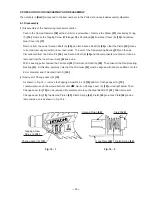
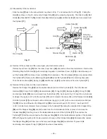
(1) Disassembly of the hammering mechanism section

Push in the Second Hammer 

[29]

 with a drill bit or a screwdriver.  Remove the Striker 

[37]

 chucked by O-ring

(C) 

[34]

.  Remove the Tapping Screw (W/Flange) D5 x 25 (Black) 

[9]

 from Gear Cover (A) 

[10]

 and remove

Gear Cover (A) 

[10]

.

Remove from the end of Second Shaft (A) 

[49]

, and turn Second Shaft (A) 

[49]

 so that the Piston 

[39]

 moves

to its maximum upper position (inner cover side).  The arm of the Reciprocating Bearing 

[51]

 can then be

disconnected from the Piston Pin 

[50]

, and Second Shaft (A) 

[49]

 and the components mounted on it can be

removed from the Inner Cover Ass'y 

[42]

 as a unit.

With a bearing puller, remove the First Gear 

[53]

 from Second Shaft (A) 

[49]

.  Then take off the Reciprocating

Bearing 

[51]

.  At this time, carefully note that the First Gear 

[53]

 must be aligned with and press-fitted onto the

9 mm diameter end of Second Shaft (A) 

[49]

.

(2) Removal of Change Lever (A) 

[19]

As shown in Fig. 16-1, remove the Tapping Screw D2.6 x 10 

[22]

 and turn Change Lever (A) 

[19]

counterclockwise (in the arrow direction) until "    " mark on Change Lever (A) 

[19]

 points right below. Then

Change Lever (A) 

[19]

 can be removed. Be careful not to lose the Steel Ball D3.97 

[23]

. After removal of

Change Lever (A) 

[19]

, the Second Pinion 

[43]

, Clutch Spring 

[44]

, Clutch 

[45]

 and Lock Plate 

[48]

 can be

removed as a unit as shown in Fig. 16-2.

9. PRECAUTIONS IN DISASSEMBLY AND REASSEMBLY

The numbers in 

[Bold]

 correspond to the item numbers in the Parts List and exploded assembly diagrams.

9-1. Disassembly

Change Lever (A) 

[19]

Second Pinion 

[43]

Tapping Screw
D2.6 x 10 

[22]

Fig. 16 - 1

Fig. 16 - 2

Clutch Spring 

[44]

Clutch 

[45]

Lock Plate 

[48]

Содержание DH 24DVA

Страница 1: ...TECHNICAL DATA AND SERVICE MANUAL SPECIFICATIONS AND PARTS ARE SUBJECT TO CHANGE FOR IMPROVEMENT LIST No G842 Mar 2006 D MODEL DH 24DVA Hitachi Power Tools CORDLESS ROTARY HAMMER DH 24DVA ...

Страница 2: ...ame Model Name DEWALT DW005K P MAKITA BHR200 C REMARK Throughout this TECHNICAL DATA AND SERVICE MANUAL a symbol s is are used in the place of company name s and model name s of our competitor s The symbol s utilized here is are as follows ...

Страница 3: ... PRECAUTIONS IN SALES PROMOTION 15 7 1 Handling Instructions 15 7 2 Caution Plates 17 7 3 Precautions Requiring Particular Attention During Sales Promotion 18 8 REFERENCE MATERIAL 19 8 1 Lubrication 19 8 2 Tool Structure 19 8 3 Three Mode Changeover Mechanism 23 8 4 Rotation Only No Hammering 25 8 5 Drill Bits 26 8 6 Tool Retainer Section 27 8 7 Dust Collector B 28 9 PRECAUTIONS IN DISASSEMBLY AND...

Страница 4: ...on with the Model DH 24DV Our rotary hammer lineup is reinforced with the new Model DH 24DVA aiming for increase of our market share 3 APPLICATIONS 1 Rotation and hammering function Drilling anchor holes Drilling holes in concrete tile brick and similar materials 2 Rotation only function Drilling holes in steel and wood with chuck adapter Tightening and loosening machine screws and wood screws wit...

Страница 5: ...e and the rotation only mode The hammering only mode is available not only for light duty chipping by means of bull points but also for groove digging and edging by means of cold chisels and cutters for various applications 4 1 2 Fastest drilling speed in the 24 V class The drilling speed of the Model DH 24DVA is equivalent to the Model DH 24DV and 1 4 times higher than C and 1 1 times higher than...

Страница 6: ...olishing concrete Demolishing blocks Suitable for demolishing hard materials such as concrete with high motor power Suitable for demolishing brittle materials such as blocks and bricks with suppressed motor power 4 1 3 Greatest demolishing performance in the 24 V class The demolishing performance of the Model DH 24DVA is 1 4 times higher than C and 1 1 times higher than P thanks to the efficient t...

Страница 7: ... 6 kg 1 3 lbs Type of motor DC magnet motor No load rotation speed POWER mode 1 050 min SAVE mode 520 min Type of switch Trigger switch with forward reverse rotation selector with brake D type handle with side handle Handle shape 5 SPECIFICATIONS 5 1 Specifications Capacity Usable drill bits 24 mm 15 16 SDS plus type only 13 mm 1 2 30 mm 1 3 16 Concrete Steel Wood Full load blow Enclosure Body Gla...

Страница 8: ...or charger is faulty During charging Prior to charging Charging completed High battery temperature Standard accessories Charging not possible Charging not possible because storage battery temperature is too high Blinks Blinks Lit Lit Flickers 0 5 sec ON 0 5 sec OFF 0 5 sec ON 0 5 sec OFF Stays ON constantly 0 1 sec ON 0 1 sec OFF Stays ON constantly Pilot lamp indications UC 24YFB ...

Страница 9: ... No 306369 306368 306370 Code No Adapter for slender shaft Drill bit slender shaft 1 Drill bit taper shank 2 Taper shank adapter SDS plus shank Drill bit taper shank 21 5 27 32 944464 Morse taper No 2 303618 3 Cotter Straight shank bit for impact drills 13 mm 1 2 hammer drill chuck SDS plus shank 13 mm hammer drill chuck For drilling operations when using a straight shank bit for impact drilling w...

Страница 10: ...r A W 5 16 Anchor setting adapter A W 3 8 Anchor setting adapter A W 1 2 Anchor setting adapter A W 5 8 Anchor setting adapter A Code No 971794 971795 971796 971797 971798 Part name W 1 4 Anchor setting adapter B W 5 16 Anchor setting adapter B W 3 8 Anchor setting adapter B W 1 2 Anchor setting adapter B W 5 8 Anchor setting adapter B Internal cone type External cone type Code No 971799 971800 97...

Страница 11: ... chuck 13VLRB D Chuck adapter G SDS plus shank Note If the tool is to be used for loosening screws open the three jaws of the drill chuck and securely fix the drill chuck to chuck adapter G with the special screw a left hand threaded M6 screw when mounting the drill chuck onto chuck adapter G Chuck wrench 321825 303623 321814 981122 Part name Drill chuck and adapter set SDS plus including a c Chuc...

Страница 12: ...ving screws rotation only Drill chuck 13VLD D NOTE The 13VLD D drill chuck and chuck adapter D cannot be used for reverse rotation If reverse rotation is to be used for loosening screws use the cross recessed head Phillips bit bit No 2 described below by attaching it directly to chuck adapter D Chuck adapter D SDS plus shank Chuck wrench Bit No Chuck adapter D SDS plus shank Phillips plus driver b...

Страница 13: ...lectric impact drill Containing 500 g 1 1 lbs Code No 980927 Containing 30 g 0 07 lbs Code No 981840 70 g 0 15 lbs Code No 308471 Code No 971787 Code No 306885 K Dust cup dust collector B Dust cup Dust collector B ass y ...

Страница 14: ...t setting Hammering only function Soft grip handle Safety slip clutch Externally accessible CB Variable speed Brake Charging time Ah Dimension Length Height kg min 346 215 4 2 60 24 2 0 316 235 4 0 40 24 3 0 Single action Single action Nicd NiMH C P 20 25 32 20 25 32 13 1 2 13 1 2 27 1 1 16 30 1 3 16 0 1 100 0 1 100 0 4 200 0 4 700 DH 24DVA 322 186 4 1 50 75 24 2 0 3 3 Single action Nicd NiMH 24 1...

Страница 15: ...2 Drilling Speed Comparisons Drilling speed depends on the operating conditions The test results shown in Fig 1 is based on actual factory tests and is used as a reference only Figure 1 shows the drilling speed comparisons for downward drilling The drill bits used are the Hitachi genuine SDS plus shank bits Fig 1 Drilling speed comparisons downward drilling ...

Страница 16: ...g performance varies considerably depending on the work conditions Use the factory test results shown in Fig 2 for comparison purposes only Fig 2 Chiseling performance comparison 1 4 3 2 5 Maker Model HITACHI DH 24DVA C P Chiseling amount kg 5 minutes ...

Страница 17: ... x 45L 240 231 215 143 C P DH 24DVA 300 HITACHI HITACHI C P DH 24DVA DH 24DV HITACHI HITACHI C P DH 24DVA DH 24DV HITACHI HITACHI C P DH 24DVA DH 24DV HITACHI HITACHI C P DH 24DVA DH 24DV HITACHI HITACHI C P DH 24DVA DH 24DV HITACHI HITACHI C P DH 24DVA DH 24DV HITACHI HITACHI C P DH 24DVA DH 24DV 16 5 mm dia x 40L 18 mm dia x 40L 12 5 mm dia x 35L 20 mm dia x 40L 24 mm dia x 40L HITACHI DH 24DV H...

Страница 18: ...ower outlet only Use of any other power source DC outlet fuel powered generator etc will cause the charger to overheat and burnout 4 Do not use any voltage increasing equipment transformer etc between the power source and the charger If the charger is used with voltage over and above that indicated on the unit it will not function properly 5 Conduct battery charging at an ambient temperature range...

Страница 19: ... to permit rapid charging Incorrect parts replacement and or wiring will cause malfunctions which could result in fire or other hazard Instruct the customer to bring these units to an authorized service center in the event repair or replacement is necessary 10 Disposal of the Models EB 2420 EB 2430H and EB 2433X batteries Ensure that all customers understand that the Models EB 2420 EB 2430H and EB...

Страница 20: ...e Plate attached to each of the Models EB 2420 and EB 2433X batteries CAUTION Read thoroughly HANDLING INSTRUCTIONS before use Do not disassemble nor throw into fire For Europe CAUTION For safe operation see instruction manual Use HITACHI charger recommended in instruction manual for recharging For the U S A anc Canada 3 The following cautions are listed on the Name Plate attached to each Model UC...

Страница 21: ...essive pressure will reduce bit rotation and hammering speed and cause the storage battery to rapidly lose its charge 3 Variation in amount of work possible per charge Although the nominal capacity of the storage batteries used with the Model DH 24DVA is 2 0 Ah the actual capacity may vary within the range of 1 8 to 2 2 Ah depending on the ambient temperature during use and recharging and the numb...

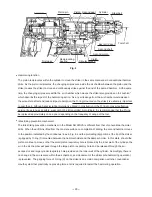
Страница 22: ... the cylinder The cylinder is coupled to the second gear by means of a slip mechanism and they rotate together The end of the cylinder also functions as the drill bit retainer The cylinder is key connected to the inserted drill bit by means of two key rails and transmits rotation to the drill bit A steel ball is used to prevent the bit from coming off Piston reciprocating mechanism In conventional...

Страница 23: ...hat the O ring be replaced approximately once a year depending on the frequency of usage of the tool Idle striking prevention mechanism The idle striking prevention mechanism in the Model DH 24DVA is different from that of conventional hammer drills When the drill bit is lifted from the concrete surface on completion of drilling the second hammer moves to the position indicated by the continuous l...

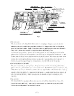
Страница 24: ...e in contact with a reinforcing bar within the concrete causing sudden excessive torque the slip mechanism functions to prevent damage to the gears and possible loss of control of the tool by the operator Sealed and dustproof construction The gear cover is totally enclosed by oil seals O rings and other devices to prevent leakage of lubricating grease and to keep dust and dirt out of the internal ...

Страница 25: ...gear cover This passage is sandwiched between felt packings to pass only air pressure Thus variations in the internal pressure are minimized for stable hammering operation and prevention of idling and grease leakage Fig 7 Felt packing Change lever Gear cover T o t h e o u t s i d e o f t h e g e a r c o v e r Air passage To the inside of the gear cover ...

Страница 26: ... claws of the reciprocating bearing A portion in the figure to convert the rotation into reciprocating motion Three claws on the tip of the second shaft engage with matching three claws of the pinion sleeve all the time and the second shaft rotation is transmitted to the pinion sleeve Then claws on the large dia portion of pinion sleeve engage with the second pinion B portion in the figure and the...

Страница 27: ...of reciprocating bearing Reciprocating bearing Lock plate rear end portion 3 Hammering only Fig 10 Adjust the change lever to hammering only mark The second pinion is moved to the motor side by the pin of the change lever Engagement between the pinion sleeve and the second pinion is released and no rotation is transmitted B portion in the figure The lock plate is moved to the motor side by spring ...

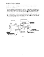
Страница 28: ...tates freely Simply turn the grip to adjust the tool to the desired position Lock plate front end portion Locking claw of second pinion Change lever 8 4 Rotation Only No Hammering The Model DH 24DVA is equipped with a change lever for changeover between rotation hammering rotation only and hammering only functions merely mounting the chuck adapter will not stop the hammering action it is absolutel...

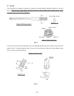
Страница 29: ...g out Key slot two pieces Key rail 2 pcs Shape of SDS plus shank bit Ball holder Steel ball Section A A Cylinder Fig 12 Section of the chuck section The service life of a drill bit with a diameter of 8 mm is approximately 300 holes when drilling into concrete with a depth of 30 mm If reground before the end of its service life the drill bit will continue to provide efficient drilling Figure 13 sho...

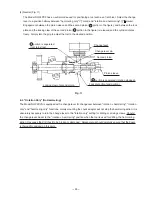
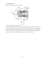
Страница 30: ...r to prevent dust and chips from getting inside The steel ball falls into the round groove of the bit to prevent the tool from coming off and the two key rails transmit the rotation torque To mount the bit push the bit in the tool retainer as far as it will go Pushing lightly turn the bit until it is caught At this position push the bit in as far as it will go sliding the grip is not required for ...

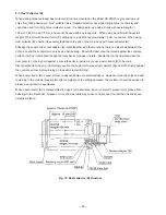
Страница 31: ...erves as a ball bearing Should the dust cover be forced against the concrete surface it will not rotate even though the tool shank continues to rotate Should the tool be operated when the dust cover is not being held against a concrete surface inertia may cause dust collector B to become disconnected from the grip Accordingly caution the customer to press dust collector B and drill bit firmly agai...

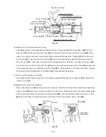
Страница 32: ...the Reciprocating Bearing 51 At this time carefully note that the First Gear 53 must be aligned with and press fitted onto the 9 mm diameter end of Second Shaft A 49 2 Removal of Change Lever A 19 As shown in Fig 16 1 remove the Tapping Screw D2 6 x 10 22 and turn Change Lever A 19 counterclockwise in the arrow direction until mark on Change Lever A 19 points right below Then Change Lever A 19 can...

Страница 33: ...econd hammer Remove the Stopper Ring 36 from the inside diameter portion of the Cylinder 17 Then the Second Hammer 29 O ring 1AP 20 30 Hammer Holder 31 O ring B 32 Damper A 33 O ring C 34 and Damper Holder 35 can be removed from the Cylinder 17 As shown in Fig 19 insert the no hole side of stopper ring jig A J 341 into the Cylinder 17 until it contacts the end surface of the Damper Holder 35 Hold ...

Страница 34: ...amage the carbon brushes The Inner Cover Ass y 42 and the Armature and Pinion Ass y DC 24 V 60 can be removed just by pressing the Pinion 55 slightly with a press because there is an interference of the O ring 58 The housing is constructed of two parts Remove the Tapping Screw W Flange D4 x 20 Black 70 to disassemble the housing 7 Removal of the carbon brush holder After disassembly of the housing...

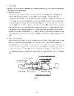
Страница 35: ...Apply Molub Alloy No 777 1 grease to the contact portion between the Clutch 45 and the Lock Plate 48 Fill Molub Alloy No 777 1 grease in the ball portion of the Reciprocating Bearing 51 Apply Hitachi Motor Grease No 29 to the O ring S 18 20 for the Steel Ball D7 0 16 and Change Lever A 19 2 Mounting the Cylinder 17 Mount the Second Hammer 29 O ring 1AP 20 30 Hammer Holder 31 O ring B 32 Damper A 3...

Страница 36: ...rk in Fig 24 and then tighten the Tapping Screw D2 6 x 10 22 Spring C 47 Fig 24 Fig 22 Fig 23 B Mounting direction Set the mark of Change Lever A 19 within the range Fit in rail A Rail B Rail A Fig 23 A Fit in rail B Fit in the inside of Spring C 47 Tapping Screw D2 6 x 10 22 tightening position Mounting position 4 Press fitting the First Gear 53 Press fit the First Gear 53 aligning with the shaft...

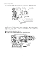
Страница 37: ...ounting Gear Cover A 10 First mount Change Lever A 19 and the lock plate ass y to Gear Cover A 10 then mount it to the main body as shown in Fig 25 At this time engage the gear in 3 points A B and C as shown in Fig 26 according to either of the following methods Mount the drill bit and turn it by a hand slowly or Install the battery and pull the trigger switch for a quick moment to turn the motor ...

Страница 38: ... wire Black Internal wire Red Internal wire Blue Internal wire Red Internal wire Black Upper side brown Lower side blue D E E 9 3 Precautions on Disassembly and Reassembly of the Charger Please refer to Technical Data and Service Manual for Model UC 24YFB for precautions on disassembly and resassembly ...

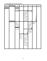
Страница 39: ...ing 608DD Brush Holder Terminal Support DC speed Control Switch Inner Cover Ass y Second Shaft A Pinion Sleeve Spring C Second Pinion Clutch Spring Clutch Lock Plate Reciprocating Bearing First Gear Ball Bearing 626VV General Assembly Housing A B Set Second Hammer O ring 1AP 20 Hammer Holder O ring B Damper A O ring C Damper Holder Cylinder Second Gear Spring A Front Cap Grip Ball Holder Holder Sp...

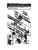
Страница 40: ...20 E1 Hitachi Power Tools 1 2 3 4 5 6 7 8 18 19 21 22 9 10 11 12 13 14 15 16 17 25 26 27 28 29 30 31 32 33 34 35 36 37 38 39 40 41 42 46 47 48 49 51 52 53 54 55 56 57 58 59 60 61 62 63 64 65 66 57 68 69 70 71 72 73 74 75 76 77 78 79 80 81 82 83 501 502 503 504 67 50 20 23 24 43 44 45 ...

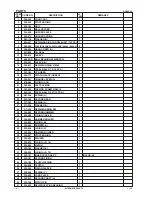
Страница 41: ...85 O RING S 18 1 21 325 554 FELT PACKING 1 22 323 239 TAPPING SCREW D2 6X10 1 23 959 155 STEEL BALL D3 97 10 PCS 1 24 981 328 SPRING H 1 25 323 185 SECOND GEAR 1 26 317 233 SPRING A 1 27 317 234 WASHER A 1 28 317 235 RETAINING RING D30 1 29 324 525 SECOND HAMMER 1 30 944 486 O RING 1AP 20 1 31 324 523 HAMMER HOLDER 1 32 322 802 O RING B 1 33 322 805 DAMPER A 1 34 322 808 O RING C 1 35 324 524 DAMP...

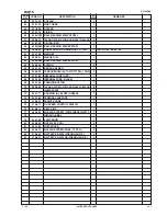
Страница 42: ...64 308 536 SPRING 2 65 323 164 BRUSH HOLDER 1 66 999 090 CARBON BRUSH AUTO STOP TYPE 1 PAIR 2 67 323 166 INTERNAL WIRE RED 1 68 323 165 INTERNAL WIRE BLACK 1 69 323 158 PUSHING BUTTON 1 70 302 086 TAPPING SCREW W FLANGE D4X20 BLACK 6 71 NAME PLATE 1 72 323 171 HOUSING A B SET GREEN 1 73 323 163 TERMINAL SUPPORT 1 74 318 247 FERRITE CORE 1 75 319 811 DC SPEED CONTROL SWITCH 1 76 319 812 HEAT SINK 1...

Страница 43: ...CHOR SETTING ADAPTER B W1 4 MANUAL 1 621 971 800 ANCHOR SETTING ADAPTER B W5 16 MANUAL 1 622 971 801 ANCHOR SETTING ADAPTER B W3 8 MANUAL 1 623 971 802 ANCHOR SETTING ADAPTER B W1 2 MANUAL 1 624 971 803 ANCHOR SETTING ADAPTER B W5 8 MANUAL 1 625 944 477 COTTER 1 626 303 617 TAPER SHANK ADAPTER SDS PLUS NO 1 1 627 303 619 A TAPER SHANK ADAPTER SDS PLUS 1 628 303 620 B TAPER SHANK ADAPTER SDS PLUS 1...

Страница 44: ...CORE BIT A 29MM 1 654 982 674 CORE BIT A 32MM 1 INCLUD 655 655 982 686 GUIDE PLATE FOR CORE BIT 32MM 1 656 982 675 CORE BIT A 35MM 1 INCLUD 657 657 982 687 GUIDE PLATE FOR CORE BIT 35MM 1 658 982 676 CORE BIT A 38MM 1 INCLUD 659 659 982 688 GUIDE PLATE FOR CORE BIT 38MM 1 660 982 677 CORE BIT B 45MM 1 INCLUD 661 661 982 689 GUIDE PLATE FOR CORE BIT 45MM 1 662 982 678 CORE BIT B 50MM 1 INCLUD 663 6...

Страница 45: ... 6 ITEM NO CODE NO DESCRIPTION REMARKS NO USED 1 06 DH 24DVA Printed in Japan 060120N ...

Страница 46: ......

Отзывы: