-19-
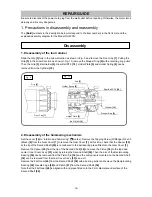
Inner Cover Ass’y
[33]
Washer (B) D12.5
[41]
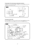
5. Reassembly of the internal pressure adjustment mechanism
As shown in Fig.13, push Felt Packing (A)
[43]
, Valve
[44]
and Felt Packing (B)
[45]
in the Inner Cover
Ass’y
[33]
as far as they will go in this order.
6. Mounting the Piston [30]
Mount the Piston
[30]
as shown in Fig. 14. At this time, mount the Thrust Plate
[28]
aligning the change
lever pocket of the Inner Cover Ass’y
[33]
with the notch of the Thrust Plate
[28]
. (See Fig. 15.)
Spring (B)
[29]
Inner Cover Ass’y
[33]
Thrust Plate
[28]
Piston
[30]
O-ring (A)
[26]
Striker
[25]
Second Shaft
[36]
Spacer
[35]
Clutch
[37]
Needle Cage
[39]
Reciprocating Bearing
[38]
First Gear
[40]
Fig. 14
A - A
Felt Packing (A)
[43]
Felt Packing (B)
[45]
Inner Cover Ass’y
[33]
Fig. 13
Valve
[44]


