--- 19 ---
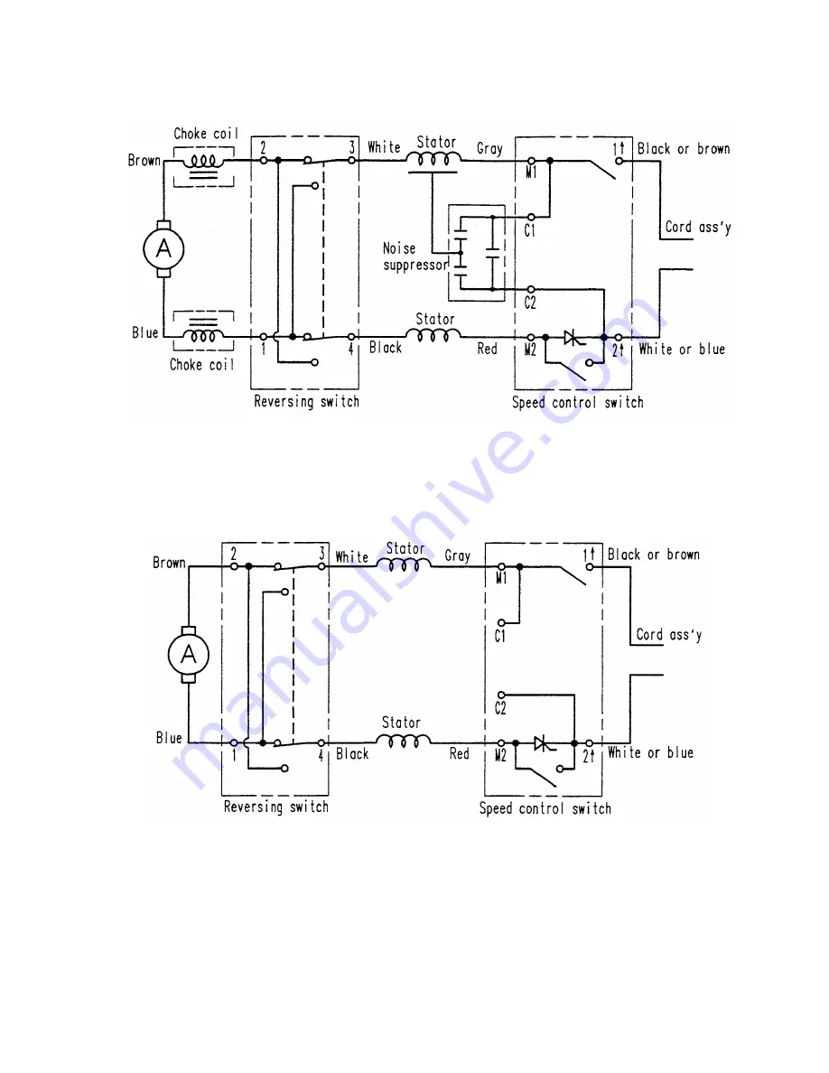
8-3. Wiring Diagrams
(1) For products with noise suppressor
(2) For products without noise suppressor
Fig. 14
Fig. 15
Страница 1: ...MANUAL 13 mm 1 2 DRILL D 13VB3 D 13VH 10 mm 3 8 DRILL D 10VJ SPECIFICATIONS AND PARTS ARE SUBJECT TO CHANGE FOR IMPROVEMENT LIST Nos D 13VB3 E107 D 13VH E108 D 10VJ E106 Nov 2004 D MODELS D 13VB3 D 13VH D 10VJ Hitachi Power Tools ...
Страница 2: ...ce of company name s and model name s of our competitor s The symbol s utilized here is are as follows Symbols Utilized Competitors Company Name Model Name BOSCH GBM13 2RE B For Models D 13VB3 and D 13VH Symbols Utilized Competitors Company Name Model Name BOSCH GBM10 2RE B For Model D 10VJ ...
Страница 3: ...LES PROMOTION 8 7 1 Handling Instructions 8 7 2 Cautions on Name Plate 8 7 3 Precautions on Usage 9 8 PRECAUTIONS IN DISASSEMBLY AND REASSEMBLY 11 8 1 Disassembly 11 8 2 Reassembly 16 8 3 Wiring Diagrams 19 8 4 Internal Wire Arrangement and Wiring Work 20 8 5 Insulation Tests 23 8 6 No Load Current Value 23 9 STANDARD REPAIR TIME UNIT SCHEDULES 24 For Model D 13VB3 24 For Models D 13VH and D 10VJ ...
Страница 4: ...and inner cover 6 Two finger sized trigger switch with speed control dial 7 Low noise 79 dB 3 APPLICATIONS 1 Rotation only function Drilling into metal wood and plastics 4 SELLING POINTS Compact and lightweight Overall length D 13VB3 339 mm 13 11 32 D 13VH 333 mm 13 1 8 D 10VJ 320 mm 12 1 32 Weight D 13VB3 2 0 kg 4 4 lbs D 13VH 1 9 kg 4 2 lbs D 10VJ 1 8 kg 4 0 lbs Shortest chuck offset 23 5 mm 15 ...
Страница 5: ...he push button type forward reverse changeover switch that is more convenient and reliable than the lever type switch In addition this switch is properly shaped and located not to make the push button an obstacle at drilling 5 Durable aluminum die casting inner cover and gear cover The Models D 13VB3 D 13VH and D 10VJ are equipped with the aluminum die casting inner cover and gear cover for increa...
Страница 6: ...ad speed Weight Net 1 Gross Packaging Standard accessories D 13VB3 AC single phase 50 60 Hz 110 V 7 6 A 230 V 3 6 A 240 V 3 5 A AC single phase commutator motor 2 core cabtire cord 2 5 m 8 3 ft Glassfiber reinforced polycarbonate elastomer Side handle 1 Depth gauge 1 Chuck wrench spec only for chuck with chuck wrench 1 Aluminum alloy die casting Variable speed control trigger switch with reversing...
Страница 7: ...et 1 Gross Packaging Standard accessories D 13VH AC single phase 50 60 Hz 220 V 3 3 A 230 V 3 2 A 240 V 3 0 A AC single phase commutator motor 2 core cabtire cord 2 5 m 8 3 ft Glassfiber reinforced polycarbonate elastomer Side handle 1 Depth gauge 1 Chuck wrench spec only for chuck with chuck wrench 1 Aluminum alloy die casting Variable speed control trigger switch with reversing switch Corrugated...
Страница 8: ...ss Packaging Standard accessories D 10VJ AC single phase 50 60 Hz 110 V 6 3A 1 220 V 3 3 A 230 V 3 2 A 240 V 3 0 A AC single phase commutator motor 2 core cabtire cord 2 5 m 8 3 ft Glassfiber reinforced polycarbonate elastomer Side handle 1 Depth gauge 1 Chuck wrench spec only for chuck with chuck wrench 1 Aluminum alloy die casting Variable speed control trigger switch with reversing switch Corru...
Страница 9: ...5 15 16 1 9 4 2 lbs 13 1 2 40 1 9 16 No load speed 13 1 2 40 1 9 16 13 1 2 40 1 9 16 13 1 2 HITACHI D 13VH min min Max torque Low High Low High 790 Rated power input 690 750 600 550 W Maker Model dB mm in mm in kg lbs D 13VB2 DUT 13 N m N m No load noise level Housing structure Gear cover material Slip clutch Soft grip handle Speed control dial Type of reversing switch Overall length Chuck offset ...
Страница 10: ...ditions The test results are based on actual factory tests and should be used as a reference only 13 mm drill class Auger bit Test material Western hemlock 10 mm drill class Auger bit Test material Western hemlock Drilling speed mm min Bit dia mm Drilling speed mm min Bit dia mm ...
Страница 11: ... electric power tool cannot be completely eliminated Accordingly general precautions and suggestions for the use of electric power tools and specific precautions and suggestions for the use of the Drill are listed in the Handling Instructions to enhance the safe efficient use of the tool by the customer Salespersons must be thoroughly familiar with the contents of the Handling Instructions to be a...
Страница 12: ...switch is pulled slightly and increases as the trigger switch is pulled more The desired rotation speed can be preselected with the speed control dial Turn the speed control dial clockwise for higher speed and counterclockwise for lower speed Fig 3 NOTE If the L side of pushbutton is pressed for reverse bit rotation the stopper cannot be used Pulling the trigger and pushing the stopper it keeps th...
Страница 13: ...it CAUTION Turn off the switch immediately if the rotation of the drill bit is stopped by the slip clutch Be careful not to actuate the slip clutch frequently The spindle shaft torque and the reactive force applied to the side handle when the slip clutch actuates are shown in the table below In the case of the low gear the reactive force applied to the side handle may be 150 4 N 15 3 kgf at the ma...
Страница 14: ...ver 33 32 32 2 Removal of the carbon brushes With a small flat blade screwdriver slightly lift the Brush Holders 38 38 38 Then while pushing the Carbon Brushes 1 Pair 37 37 37 to the bottom of the brush holders gently pull out and disconnect the internal wire terminals See Figs 4 and 5 3 Removal of the gear cover from the housing Loosen the Tapping Screws W Flange D5 x 50 8 D5 x 45 8 8 and separat...
Страница 15: ... Removal of the stator from the housing First disconnect the internal wires from the Switch 35 34 34 To disconnect the internal wires from the switch insert a small flat blade screwdriver into the windows near the terminals and pull out the internal wires Remove the Hex Hd Tapping Screws D4 x 50 26 D4 x 45 25 25 and tap the end surface of the Housing 30 29 29 slightly with a wooden hammer Then the...
Страница 16: ...the drill chuck until the wrench is at about a 30û angle to the bench top and strike the wrench sharply with a hammer so the drill chuck turns in the counterclockwise direction Fig 7 Pipe Hex bar wrench Fig 8 Turn it counterclockwise Vise Open end wrench b Hold the Spindle 4 4 4 with the open end wrench secured to the vise as shown in Fig 8 Mount the pipe to the hex bar wrench Turn the hex bar wre...
Страница 17: ...and ring J 78 Vise Turn it counterclockwise Wrench ass y J 140 Drill chuck Fig 9 8 1 3 Gear cover section disassembly 1 Removal of the spindle Remove the Retaining Ring For D35 Hole 5 5 5 Support the tip of Gear Cover A 9 9 9 with a cylindrical jig of inside diameter 35 mm or more and push the rear portion of the Spindle 4 4 4 lightly Then the spindle can be removed together with the Ball Bearing ...
Страница 18: ... 180 degrees together with the Retaining Ring E type for D15 Shaft 18 18 18 Insert a flat blade screwdriver into the clearance and pry the Retaining Ring E type for D15 Shaft 18 18 18 off upward NOTE If the Retaining Ring E type for D15 Shaft 18 18 18 is pushed excessively the Shift Lever Ass y 15 15 15 cannot be turned due to a wide clearance Clearance Gear Cover A 9 9 9 Shift Lever Ass y 15 15 1...
Страница 19: ...Gear Set 11 11 11 and the Gear Set 21 21 21 On the Spindle 4 4 4 Ground portion for fitting the Ball Bearing 6202DDCMPS2L 6 6 6 splined portion and hole of rear side On the Shift Lever Ass y 15 15 15 Outer circumference portions of the Shift Pin 14 14 14 and the O ring S 22 13 13 13 On the Inner Cover 12 12 12 Metal portion Inside of Gear Cover A 9 9 9 5 g 8 2 3 Tightening torque 1 Flat Hd Scerw A...
Страница 20: ...ion and Gear Set 11 11 Washer B 10 10 Fig 12 Shift Arm 19 19 Pin D5 20 20 Steel Ball D3 5 17 17 Gear Set 21 21 Spring H 16 16 Shift Lever Ass y 15 15 Ball Bearing 6202DDCMPS2L 6 6 Spindle E 4 4 Retaining Ring for D35 Hole 5 5 CAUTION Mounting directions of the Shift Arm 19 19 and the Gear Set 21 21 are specified Mount these parts in the specified directions as shown in the above figure ...
Страница 21: ...ing H 16 are specified Mount these parts in the specified directions as shown in the above figure Second Pinion and Gear Set 11 Washer B 10 Fig 13 Shift Arm 19 Pin D5 20 Steel Ball D3 5 17 Gear Set 21 Spring H 16 Shift Lever Ass y 15 Ball Bearing 6202DDCMPS2L 6 Spindle D 4 Retaining Ring for D35 Hole 5 ...
Страница 22: ... 19 8 3 Wiring Diagrams 1 For products with noise suppressor 2 For products without noise suppressor Fig 14 Fig 15 ...
Страница 23: ... 20 8 4 Internal Wire Arrangement and Wiring Work A Internal wire arrangement 1 For products with noise suppressor Noise suppressor Fig 16 ...
Страница 24: ... 21 2 For products without noise suppressor Fig 17 ...
Страница 25: ... 22 B Switch connection 1 Wiring of reversing switch 2 Wiring of speed control switch Fig 18 Fig 19 ...
Страница 26: ...ute with no abnormalities 220 V 240 V and 110 V for U K products AC 2 500 V 1 minute with no abnormalities 110 V 127 V except U K products 8 6 No Load Current Value After no load operation for 30 minutes the no load current value should be as follows Voltage V Current A Max 1 6 230 1 5 240 1 7 220 Voltage V Current A Max 1 5 240 3 5 110 1 6 230 Model D 13VB3 Model D 13VH Voltage V Current A Max 1 ...
Страница 27: ... Flow 60 min 50 Handle Cover Cord Armor Housing Stator Armature Ball Bearing 608DD Ball Bearing 698T1 General Assembly D 13VB3 Drill Chuck Switch Cord Inner Cover A Second Pinion and Gear Set Spindle D Ball Bearing 6202DD Gear Cover A Shift Lever Ass y Spring H Shift Arm Gear Set ...
Страница 28: ... Cover Cord Armor Housing Stator Armature Ball Bearing 608DD Ball Bearing 698T1 General Assembly D 10VJ Drill Chuck Switch Cord Inner Cover B Second Pinion and Gear Set Spindle E Ball Bearing 6202DD Gear Cover A Shift Lever Ass y Spring H Shift Arm Gear Set D 13VH ...
Страница 29: ...RTS LIST LIST NO E107 DRILL Model D 13VB3 2004 11 15 E1 Hitachi Power Tools 1 2 3 4 5 6 7 8 10 11 12 13 14 15 16 17 9 18 19 20 21 23 24 25 26 27 28 29 30 31 33 34 36 37 38 39 32 40 41 42 43 44 501 502 3 22 10 45 46 35 ...
Страница 30: ...T 1 19 322 849 SHIFT ARM 1 20 984 104 PIN D5 1 21 322 846 GEAR SET 1 22 LABEL FOR SLIP CLUTCH 1 23 608 DDM BALL BEARING 608DDC2PS2L 1 24 360 652C ARMATURE 110V 1 24 360 652E ARMATURE 230V 1 24 360 652F ARMATURE 240V 1 25 322 843 FAN GUIDE 1 26 961 672 HEX HD TAPPING SCREW D4X50 2 27 340 587C STATOR 110V 1 27 340 587E STATOR 230V 1 27 340 587F STATOR 240V 1 28 698 T1X BALL BEARING 698T1XZZ1MC2E NS7...
Страница 31: ...1 04 D 13VB3 45 953 327 CORD ARMOR D8 8 1 46 500 409Z CORD 1 CORD ARMOR D8 8 46 500 247Z CORD 1 CORD ARMOR D8 8 FOR FIN NOR SWE DEN 46 500 439Z CORD 1 CORD ARMOR D8 8 FOR NZL AUS 46 500 461Z CORD 1 CORD ARMOR D8 8 FOR GBR 110V 46 500 435Z CORD 1 CORD ARMOR D8 8 FOR GBR 230V ...
Страница 32: ... ALTERNATIVE PARTS 4 ITEM NO CODE NO DESCRIPTION REMARKS NO USED 11 04 D 13VB3 STANDARD ACCESSORIES Printed in Japan 041115N 501 323 050 SIDE HANDLE 1 502 303 709 DEPTH GAUGE 1 ...
Страница 33: ...TS LIST LIST NO E108 DRILL Model D 13VH 2004 11 15 E1 Hitachi Power Tools 1 2 3 4 5 6 7 8 10 11 12 13 14 15 16 17 9 18 19 20 21 22 23 24 25 26 27 28 29 30 32 33 34 35 36 37 38 39 31 40 41 42 43 44 45 46 47 501 502 3 10 ...
Страница 34: ...SET 1 22 608 DDM BALL BEARING 608DDC2PS2L 1 23 360 655E ARMATURE 220V 230V 1 23 360 655F ARMATURE 240V 1 24 322 843 FAN GUIDE 1 25 981 824 HEX HD TAPPING SCREW D4X45 2 26 340 589E STATOR 220V 230V 1 26 340 589F STATOR 240V 1 27 698 T1X BALL BEARING 698T1XZZ1MC2E NS7L 1 28 309 929 RUBBER BUSHING 1 29 322 861 HOUSING 1 30 NAME PLATE 1 31 301 653 TAPPING SCREW W FLANGE D4X20 BLACK 3 32 322 862 HANDLE...
Страница 35: ... ALTERNATIVE PARTS 3 ITEM NO CODE NO DESCRIPTION REMARKS NO USED PARTS 11 04 D 13VH 47 500 423Z CORD 1 CORD ARMOR D8 8 FOR KUW SIN 47 500 468Z CORD 1 CORD ARMOR D8 8 FOR CHN ...
Страница 36: ...ORIES ITEM NO CODE NO DESCRIPTION REMARKS NO USED STANDARD ACCESSORIES ITEM NO CODE NO DESCRIPTION REMARKS NO USED D 13VH Printed in Japan 041115N 501 323 050 SIDE HANDLE 1 502 303 709 DEPTH GAUGE 1 601 321 814 DRILL CHUCK 13VLRB D 1 INCLUD 1 2 ...
Страница 37: ...S LIST LIST NO E106 DRILL Model D 10VJ 2004 11 15 E1 Hitachi Power Tools 1 2 3 4 5 6 7 8 10 11 12 13 14 15 16 17 9 18 19 20 21 22 23 24 25 26 27 28 29 30 32 33 34 35 36 37 38 39 31 40 41 42 43 44 45 46 47 501 502 3 1 10 ...
Страница 38: ...RM 1 20 322 860 PIN D5 1 21 322 846 GEAR SET 1 22 608 DDM BALL BEARING 608DDC2PS2L 1 23 360 655C ARMATURE 110V 1 23 360 655E ARMATURE 220V 230V 1 23 360 655F ARMATURE 240V 1 24 322 843 FAN GUIDE 1 25 981 824 HEX HD TAPPING SCREW D4X45 2 26 340 589C STATOR 110V 1 26 340 589E STATOR 220V 230V 1 26 340 589F STATOR 240V 1 27 698 T1X BALL BEARING 698T1XZZ1MC2E NS7L 1 28 309 929 RUBBER BUSHING 1 29 322 ...
Страница 39: ...GE D4X16 2 45 937 631 CORD CLIP 1 46 953 327 CORD ARMOR D8 8 1 47 500 409Z CORD 1 CORD ARMOR D8 8 47 500 447Z CORD 1 CORD ARMOR D8 8 FOR SYR 47 500 439Z CORD 1 CORD ARMOR D8 8 FOR NZL AUS 47 500 470Z CORD 1 CORD ARMOR D8 8 FOR TPE 47 500 468Z CORD 1 CORD ARMOR D8 8 FOR CHN 47 500 435Z CORD 1 CORD ARMOR D8 8 FOR HKG ...
Страница 40: ...ES ITEM NO CODE NO DESCRIPTION REMARKS NO USED STANDARD ACCESSORIES ITEM NO CODE NO DESCRIPTION REMARKS NO USED D 10VJ Printed in Japan 041115N 501 323 050 SIDE HANDLE 1 502 303 709 DEPTH GAUGE 1 601 322 370 DRILL CHUCK 10VLRG N W O CHUCK WRENCH 1 ...
Страница 41: ......