background image


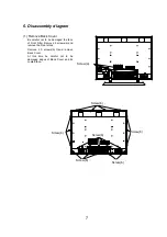
6. Disassembly diagram 


(1) Remove Back Cover


Be careful not to be damaged the face 
of Front Filter. Remove 4 screws(a) and 
remove the Rear stand. 

  Remove 20 screws(b) 

and remove 

Back Cover. 

  At this time be careful not to be 

damaged edges of Back Cover and its 
coated face. 


7


LISTED

7J88

UL1950

WARNING/AVERTISSEMENT/VO RSICHT/PRECA UCION

S/N

JUNE/JUIN  1999

Y9G000001

CMP402HD

100‑120V/220‑240V〜
50‑60Hz, 5A/2.5A

US

C

2

PLASMA DISPLAY/ECRAN A PLASMA
MOD. NO./MOD. N .

o

必ずア−ス接続を行って下さい。

(MONO)

RG B 1

〔 D − S U B 〕

RGB2〔BNC〕

RGB INPUT

AUDIO

L0

90

01

RS232C IN

Screw(a)

V I DE O 2  I N P U T

A UD I O

(MONO)

〔 C O M P O NE N T 〕

P   / C

P /C

VI D E O

S − VI D E O

VIDEO1 INPUT

(MONO)

AUDIO


Screw(a) 


Q L0 90 01

RS232C IN

(MONO)

R G B1

〔 D − SU B 〕

RGB2〔BNC〕

RGB INPUT

AUDIO

Screw(b)

Screw(b)

Screw(b)

Screw(b)

Screw(b)

Screw(b)

V I D E O 2 I N P U T

A U D I O

(MONO)

〔 C O M P ON E N T 〕

P   / C

P /C

V I D E O

S− V I D EO

V ID E O 1  I NP U T

(MONO)

AUDIO


Screw(b) 

Screw(b) 

Screw(b) 

Screw(b) 

Screw(b) 

Screw(b)   

Содержание CMP307XE

Страница 1: ...ficiently cool 3 Special care shall be taken to the display area in order not to damage its surface 4 The Panel Module shall not to be touched with bare hand to protect its surface from stains 5 It recommended to use clean soft gloves during the replacing work in order to protect not only the display area of the Panel Module but also a serviceman himself 6 The Chip Tube of Panel Module located upp...

Страница 2: ...deo for S2 NTSC3 58 Video Composite 1 0 V S video Y 1 0 Vp p C 0 29Vp p Sync Composite sync Input Signal Video 2 RCA Pinx3 Component Video Y Pb Pr or Y Cb Cr 480i 480P 1080i 1035i Video Y 1 0 Vp p Pb Cb Pr Pr 0 7 Vp p Sync Superimposed with Y signals Colors 2 09 million Synchronization Horizontal 24 64 kHz Vertical 50 75 Hz Resolution Horizontal 1024 dots max Vertical 768 lines max Viewable Image ...

Страница 3: ... LU M E S T A N D B Y R E D O N G R N HI TACHI FRONT VIEW Front Frame Power Switch Control Switches STAND Front Filter L ISTED 7J88 U L1950 WA RNI NG A VE RT I SS EM EN T VOR SI CH T P RE CA UC IO N S N JUNE JUIN 1999 Y9G000001 CMP402HD 10 0 120V 2 20 240V 50 60Hz 5 A 2 5A US C 2 P L A S M A D I SP L A Y E C RA N A P L A S M A M O D N O MO D N o 必ずア ス接続を行って下さい MO NO L R V H B G R RGB 1 D S UB RGB2...

Страница 4: ...is not light Is the input voltage applied to the AC DC Power unit PESW1 4 6 No Yes AC inlet Power switch AC Fuse F911 10A250V 7 5 6V 11 4 4V 9 GND AC DC Power unit No Yes Picture is displayed But no sound Are Voltage applied to pins 4 PSD3 of the Signal PWB No AC DC Power unit 4 14V 5 GND No Are there signals on Speaker Signal PWB 4 ...

Страница 5: ...er unit Signal PWB AC DC Power unit Do the Fans rotate When disconnect PF1 3 of the AC DC Power unit the picture Is displayed DC Fan AC DC Power unit Is Voltage of the pin 5 PED on the AC DC Power unit 5V AC DC Power unit Are Voltages of the pin 1 PEY1 on the AC DC Power unit collect Is Voltage of the pin 9 11 PED on the AC DC Power unit collect Panel Module Panel Module AC DC Power unit Are Volta...

Страница 6: ... 1 1 1 12 12 1 1 1 1 1 1 1 1 1 1 12 12 1 1 8 1 7 7 1 1 13 19 11 1 7 7 5 5 5 5 3 3 PSS 1 45 45 1 PY01 PY03 PY02 PY04 45 1 45 40 1 40 1 40 1 1 1 1 1 13 19 11 40 1 40 1 1 40 1 1 1 5 5 5 1 5 5 5 PDY PDY PDY PDY PDY PDY PDX PDX PDX PDX PDX PDX 40 1 40 1 40 1 40 1 40 1 40 1 40 1 40 1 40 1 180v VADR 70V 5V VADR 70V 14V 5V VSUS 180V VXSC 60V VRES 340V VADR 70V VXSC 60V VRES 340V VYSC 70V VYSB 170V 14V 5V ...

Страница 7: ...240V 5 0 60Hz 5A 2 5A U S C 2 PLASMA DISPLAY ECRAN A PLASMA MOD NO MOD N o 必ずア ス接続を行って下さい MONO L R V H B G R RG B 1 D S U B RGB2 BNC RGB INPUT AUDIO Q L 0 9 0 0 1 R S232CIN Screw a V I DE O 2 I N P U T R L R B Y AUDIO M ONO B COMPONENT R P C P C R L VI D E O S VI D E O V IDEO1 INP UT MONO AUDIO Screw a Q L0 90 01 RS232 CIN MONO L R V H B G R R G B1 D SU B RGB2 BNC RGB INPUT AUDIO Screw b Screw b S...

Страница 8: ...lastic rivet 4screws e 2screws g and remove Signal PWB and Video PWB 3 Remove filter PWB Disconnect P902A PESW1 connector Remove 4screws d and remove the filter cover Then remove 4screws g and remove Filter PWB 8 SIGNAL PWB VIDEO PWB Screw c Screw Screw c Screw c Screw f Plastic rivet Screw g Screw e Screw e Screw f Screw e Screw e Screw g Plastic rivet Screw f Screw f Screw d Screw g Filter Cover...

Страница 9: ...t to fall down the front Filter When remove the filter hold Metal When attach the new Front Filter remove protection film on a side yellow tag is marked Then attach to the Front Frame locating the conducting electrode side to the inside and attach Filter hold Metal Screw m Screw m Screw m Screw m Main frame Screw m Screw m Front Filter Glass Screw m Screw m Front Filter Glass Screw m Screw m Screw...

Страница 10: ...tic rivets 7 Remove AC DC Power unit Remove 4 screws o and 2 screw p then disconnect PESW1 VH 6P PEY1 VH 5P PED EH 12P PF1 EH 3P PF2 EH 3P PF3 EH 3P connectors 10 Prastic rivet Fan Metal Screw k AEF6 BEF6 connector Plastic rivet AEF6 BEF6 Connector Screw k Fan Metal Screw o Screw p Screw o Screw p Fan Metal ...

Страница 11: ...set to black point 6 Set Adjustment No 43 to changing point from black to Blue set to black point 7 Input all white level Signal 8 Set Adjustment No 44 to changing point from Red to black set to black point 9 Set Adjustment No 45 to changing point from Green to black set to black point 10 Set Adjustment No 46 to changing point from Blue to black set to black point Tolerances of each color adjustme...

Страница 12: ...undamental amplitude adjustment How to Prepare 1 Connect Video input NTSC 3 58 Video level 0 714Vp p Sync level 0 286Vp p no set up 2 Appear and Adjust screen OSD Menu of Picture Contrast 127 Brightness 0 Video level NORMAL Color Select MID How to Adjust 1 Set Service Adjust Mode and adjust as follows by Remote Control Transmitter 2 Set Adjustment No 35 36 and 37 scale to 255 3 Input all black lev...

Страница 13: ...ORM x 0 287 0 002 y 0 287 0 002 at 9400K 5 Adjust color temperature as follows by increasing or reducing numbers of NO 38 39 40 Video color temperature WARM x 0 314 0 002 y 0 315 0 002 at 6500K Suggestion 1 Luminance of panel surface is less than 20lux to arrange adjustment environment 2 Color select mode is automatically set to COOL while adjustmentNo 32 33 and 34 3 Color select mode is automatic...

Страница 14: ...THE UPDATED PARTS LIST FOR THIS MODEL IS AVAILABLE ON ESTA ...

Страница 15: ... ITALY Tel 39 02 487861 Tel 39 02 38073415 Servizio Clienti Fax 39 02 48786381 2 Email customerservice italy hitachi eu com HITACHI Europe AB Box 77 S 164 94 Kista SWEDEN Tel 46 0 8 562 711 00 Fax 46 0 8 562 711 13 Email csgswe hitachi eu com HITACHI EUROPE S A S Lyon Office B P 45 69671 BRON CEDEX FRANCE Tel 04 72 14 29 70 Fax 04 72 14 29 99 Email france consommateur hitachi eu com HITACHI EUROPE...

Отзывы: