background image

R400

51K

R609

2.7K

1/4W

2SC945

Q405

GND

GND

(FUSE)

1/2W

47

R614

R449

(FUSE)

47 1/4W

33K

R605

2W

1

R607

+

C603

105C

25V

2200U

R601

100

1/4W

+

10U

C730

GND

R613

1/4W

10

2SC945

Q731

R402

1/4W

100

R416 100

1N4148

D611

MEF

.1U

C448

R417

(FUSE)

1/4W

10

R468

10K

GND

GND

Q424

2SA733

1N4148

D420

+

2.2U

C606

1N4148

D431

R410

33K

2SC945

Q414

1N4148

D612

R403

47K

1/4W

R436

56K

4

3

2

1

P501

+

C446

16V

470U

R443

1/4W

2.2K

2SC945

Q417

2SA733

Q416

2SC945

Q412

R610

12K

GND

220P

C613

1N4148

D405

R404

1%

6.2K
1/4W

GND

1/2W

180

R611

.1U

C602

GND

100uH

L611

GND

GND

+

1U

C605

10K

R478

+

C408

16V

470U

R431

1%

1.24K

1K

R476

R432

1%

750

GND

R465

1/4W

120K

GND

1K

R477

2SC945

Q432

GND

GND

R461

1/4W

36K

R422

(FUSE)

1/4W

1.5K

MEF

.1U

C471

1K

R475

150p

C470

1K

R474

1/4W

(FUSE)

2.2K

R473

GND

2SC2001

Q431

2.2K

R734

GND

GND

GND

+

25V

22U

C411

1N4148

D421

2SC945

Q406

470P

C404

10K

R453

1/4W

100K

R452

GND

Q428

XX

XX

C455

220P

C440

470K

1/4W

R405

GND

6.8K

R456

GND

4.7k

R455

GND

GND

220K

R457

33K

R462

220K

R450

GND

GND

AN5767K

13

12

11

10

9

8

7

6

5

4

3

2

1

U402

22K

R463

200K
1/4W

R469

1N4148

D404

GND

FR104

D491

GND

GND

150K

R441

MEF

.01U

C438

PPN

.01U

C415

R429

8.2K

(FUSE)

220

1/4W

R491

1%

4.3K

1/4W

R731

MEF

.01U

C410

MEF

.1U

C422

R428

1%

22K

C413

PPN

.0022U

.1U

MEF

C412

250V

MEF

.1U

C512

R423 39K 1/4W

9

8

7

6

5

4

3

2

1

U601

TDA8351

R447

430k

1/4W

R430

10K

R419

3.3K

TDA4858

U401

+

16V

470U

C491

R408
150K
1/4W

R606

1/4W

10K

100P

C443

C406

25V NP

10U

GND

GND

56K

1/4W

R454

HZ5C1

ZD404

2%

1500P

MEF

C428

22K

1/4W

R459

Q442

2SD667

+

C427

16V

100U

R732

1%

7.32K

GND

R437

620K

R420

27K

GND

R407

1/4W

13K

+

C604

63V

100U

+

-

470P

C433

GND

MEF

.01U

C416

R406

2.2M

R471

1%

18.2K

R409
270K

1N4148

D430

R466

1/4W

680K

MEF

.012U

C417

20K

VR405

R444
330K

1/4W

100

R621

R418

1.2K
1/4W

GND

GND

R442

4.7K

R434

150K 1/4W

R494

1/4W

100

R440

270K

2SC945

Q438

.1U

C432

2SC945

Q413

2SC945

Q411

2SC945

Q409

2SC945

Q407

1%

5.36K

R623

10K

1/4W

R411

GND

2SA733

Q732

GND

GND

2SC945

Q404

GND

HZ12C1

ZD442

R481

10K

MEF

.1U

C424

250V

MEF

.1U

C435

GND

R427

56K

1/4W

+

C437

16V

100U

XX

C601

GND

2SC945

Q410

1/4W

10K

R412

+

-

U403

LM358

MEF

.01U

C434

R733

1K

47K

1/4W

R426

GND

100

R620

Q401

RN1203

HZ12C1

ZD730

R730

1%

5.11K

R482

4.7K

MEF

.22U

C414

10K

R736

GND

GND

GND

2

1

P730

1%

9.09K

1/4W

R472

HZ12C1

ZD491

R413

1%

22.1K

10K 1/4W

R480

100P

C444

1%

7.15K

1/4W

R464

240K

1/4W

R401

1N4148

D494

(FUSE)

1/4W

2.2

R489

R424

47K

R603

100

1/4W

Q420

2SC945

XX

R487

2SC945

Q408

2SC945

Q430

Q422

2SA733

R604

1W

1

R451

2.2K

1/4W

H-DRIVE

5V

5V

V-OUT

V-OUT

CLAMP

H-BLK

U601-P9

V-MORIE

H-MORIE

MUTE

CORNER

V-MODE

HFLB

HFLB

BLANCE

42V

15V

V350

FBP

PIN

X-RAY

V-SIZE

H-OUT

V-DF

G1

TRAP

H-PHASE

V-CENT

12V

12V

12V

B-DRIVE

Q814-E

15VS

15VS

X-RAY

H-SIZE

43V

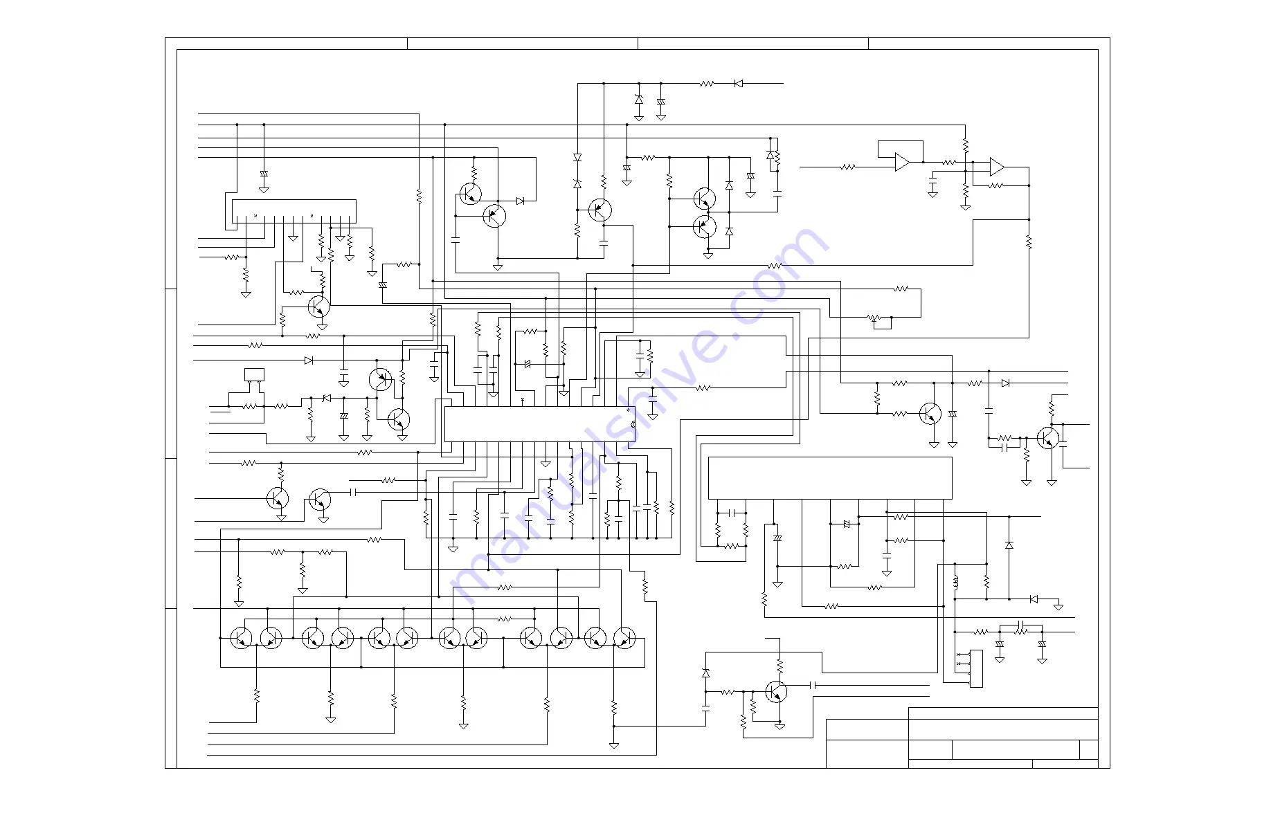
SWITCH BOARD VR-916

SCHEMATIC, DEF & POWER VA-916/

Title


PIN 26

FORM U401

PARALLEL

1

2

3

4

D

C

B

A

7

6

5

3

2

1

32

31

30

29

28

27

26

25

24

23

22

21

20

19

18

17

16 15 14 13 12 11 10 9 8 7 6 5 4 3 2

N0 NOTES ? V CAPACITOR IS 50V

NO NOTES ? W RESISTOR IS 1/8W

446A49-01

FOR 456A49-01

HITACHI (EUROPE) LTD

Sheet 2 of 3

Содержание CM721FET

Страница 1: ...Service Ingenieur die Sicherheitshinweise und Hinweise zur Produktsicherheit in diesem Wartungshandbuch zu lesen SERVICE MANUAL MANUEL D ENTRETIEN WARTUNGSHANDBUCH Data contained within this Service manual is subject to alteration for improvement Les données fournies dans le présent manuel d entretien peuvent faire l objet de modifications en vue de perfectionner le produit Die in diesem Wartungsh...

Страница 2: ...e without danger of electrical shock The service technician must make sure that no protective device built into the instrument by the manufacturer has become defective or inadvertently damaged during servicing CE MARK 1 HITACHI products may contain the CE mark on the rating plate indicating that the product contains parts that have been specifically approved to provide electromagnetic compatibilit...

Страница 3: ...n doit s assurer qu aucun des dispositifs de protection intégrés à cet instrument par le fabricant n est défectueux ou n a été endommagé de façon accidentelle lors de l entretien LABEL CE 1 Les produits HITACHI peuvent avoir reçu le label CE qui figure sur la plaque signalétique pour indiquer que cet ensemble contient des composants qui ont fait l objet d une homologation spécifique de respect des...

Страница 4: ...ass keine vom Hersteller im Gerät eingebaute Schutzvorkehrung schadhaft geworden ist oder bei der Wartung unabsichtlich beschädigt wurde CE KENNZEICHEN 1 HITACHI Produkte enthalten eventuell das CE Kennzeichen auf dem Leistungsschild welches angibt dass das Produkt Teile enthält die eigens zugelassen sind um bis zu einem spezifizierten Niveau elektromagnetische Störfreiheit zu bewirken 2 Wenn Sie ...

Страница 5: ...NT 7 2 CONTROLS AND CONNECTORS LAYOUT 10 A MAIN PCB 10 B CRT B 11 C PIN ASSIGNMENT 11 3 CIRCUIT DESCRIPTION 12 A POWER SUPPLY 12 B POWER SUPPLY BLOCK DIAGRAM 12 C POWER SUPPLY CIRCUIT 13 D TDA4855 4858 AUTOSYSNC DEFLECTION CONTROLLER 14 FIGURE 4 5 14 E HORIZONTAL PROCESSOR 16 F VERTICAL PRE AMP 16 G HORIZONTAL DRIVE 17 4 TROUBLESHOOTING 18 A MONITOR CHECK FLOW CHART 19 APPENDIX A SCHEMATIC DIAGRAM...

Страница 6: ...e properly adjusted at 15 F L with full intensity reverse pattern then switch to cross hatch pattern and place unit facing east Pincushion should be less than 2 0mm Barrel should be less than 2 0mm top bottom 1 5 left side right side Trapezoid should be less than 3 5mm Parallelogram should be less than 3 5mmTilt should be less than 1 2 degree E Alignment Procedure E 1 Brightness Adjust 1 Adjust th...

Страница 7: ... 3 with full white pattern adjust OSD ABL SUB BRIGHTNESS to get full white light output 30 2 FL G Focus Adjustment G 1 Adjust brightness have the brightness of raster be 0 06FL and contraset be 30FL in timming 6 G 2 Adjust the G4a and G4b of theFBT have focus be in the best condition on the 1 4 diagonal of screen in timing 5 H Convergence Adjustment Input R B and R G signals make sure convergence ...

Страница 8: ...rted all output voltage should be shut down and unlatch 3 when normal condition is recovered all output voltage should recover automatically J 4 Side Pincushion Tilt and Geometry Distortion Adjustment 1 Input timing 1 adjust the display be normal position and size 2 Adjust front control key to get the best pincushion distortion and tilt 3 Select P502 and adjust VR402 VR404 to get the best geometry...

Страница 9: ... 70 09 31 78 14 27 25 422 12 711 1 907 1 112 3 813 0 064 0 636 0 381 4 VESA60 800 600 40 P P 37 88 60 32 26 4 16 58 20 15 84 2 2 0 607 3 2 0 106 1 0 025 5 VESA85 800 600 56 25 P P 53 674 85 061 18 631 11 756 14 222 11 179 2 702 0 503 1 138 0 056 0 569 0 019 6 VESA60 1024 768 65 N N 48 36 60 20 68 16 67 15 754 15 88 2 462 0 6 2 092 0 124 0 369 0 063 7 VESA75 1024 768 78 75 P P 60 023 75 029 16 66 1...

Страница 10: ... 9 ...

Страница 11: ... 10 2 CONTROLS AND CONNECTORS LAYOUT A Main PCB ...

Страница 12: ...H CENTRE VR P701 TILT CONN JP1 PRESET CONN P902 DEGAUSSING COIL CONN P703 X RAY TEST PAD P302 P303 P301 P5 1 HFLB Vout DSUB9 DDC SCL 2 GND EEP SCL R IN DDC SDA 3 G1 EEP SCL GND GND 4 6 3V H OUT B IN V SYNC 5 5V GND GND H SYNC 6 76V G IN 7 12V GND 8 CONTRAST ...

Страница 13: ... power supply is a universal switching mode power supply It consists of an off line flyback converter and a Boost converter The output voltage and current rating are 7 5V 0 81A 15 3V 0 84A 44V 0 2A 76V 0 2A and B 202V 0 4A B Power Supply Block Diagram ...

Страница 14: ...Q902 low by delaying the voltage rise until drain current has decreased from its peak value This snubber also damps out any ringing which may occur due to parasitic C 3 SYNCHRONIZED CIRCUIT The oscillator frequency is defined by R912 C920 The equation is approximately Fosc 1 8 R912 C920 The external signal that comes from horizontal circuit synchronises the working frequency of power circuit Via U...

Страница 15: ...er circuit The feedback points of U991A is not only connected to C906 but also the AC line in voltage of C901A which the voltage waveform shape is same as the line in voltage The follower booster circuit can smooth the input current to improve PF value D TDA4855 4858 AUTOSYSNC DEFLECTION CONTROLLER Figure 4 5 ...

Страница 16: ...utput VPOS 17 V shift input VAMP 18 V size input VSCOR 19 vertical S correction input EWTRP 20 Ew trapezium correction input EWPAR 21 Ew parabola amplitude input VAGC 22 external capacitor for V amplitude control VREF 23 external resistor for vertical oscillator VCAP 24 external capacitor for vertical oscillator GNDS 25 ground signal ground HPLL1 26 external filter for PLL 1 HBUF 27 buffered f v v...

Страница 17: ...he free run frequency is setting by R428 and C412 fvo 1 10 8 x R428 x C412 C445 the V position is controlled by the D C pin 17 and V size is controlled by D C pin 18 and the pin 19 is to ADJ VERT linearity F 1 VERT output circuit U601 TDA 8351 see Figure 6 The saw tooth is output from U401 pin 12 13 to the pins 1 and 2 of TDA8351 vert output amplifier and then output from pin 7 to the vert DY for ...

Страница 18: ...FBT and input to U801 PWM modulator IC to drive Q801 When Q801 turns on the energy is stored in the FBT When Q801 turns off the resonate circuit creates a pulse to the FBT to generate a HV 25KV 26KV and G5 voltage 6 1 7 8KV and G1 voltage 180V and 32V for X RAY protection and 300V for dynamic focus H Video Amp Circuit H 1 Video PRE AMP U301 M52743 is the Video PRE AMP The input signal is 0 7Vp p t...

Страница 19: ...en R932 R963 DB901 DB904 Is Check and repair Q903 U903 Q903 VDS No D982 M907 M911 D912 Waveform normal Is 7 5V No Check Q902 D926 C937 In spec U904 U908 VR901 Q909 Is B voltage No Check Q902 Q921 D924 U902A Correct Q909 202V Ready is Combine with Monitor check operation frequency OK Stop ...

Страница 20: ... 19 A Monitor Check Flow Chart A 1 No raster ...

Страница 21: ... 20 A 2 No Picture ...

Страница 22: ... 21 A 3 No vertical deflection raster become a horizontal line ...

Страница 23: ... 22 APPENDIX A SCHEMATIC DIAGRAMS PCB ASSEMBLIES ...

Страница 24: ...L30 BEAD 8MHz Y1 GND SW1 R1 4 7K R13 100 SW5 10V 100U C9 SW4 SW3 SW2 GND 100P C40 O G I 7805 U3 R4 1 5 1K 5 4 3 2 1 P3 R69 10K R8 1 10K 4 7K R80 4 3 2 1 P2 2SC945 Q1 2W 3 3 R100 C25 4 7U R68 10K R14 100 4 7U C29 4 7U C30 4 7U C21 4 7U C20 4 7U C19 5 6k R35 220P C37 GND GND 4 7U C24 BEAD L8 BEAD L7 XX R73 BEAD L5 BEAD L6 1N4148 D8 1N4148 D6 GND GND 1N4148 D7 1N4148 D9 GND 1N4148 D11 1N4148 D10 1N41...

Страница 25: ...W 10K 100P C443 C406 25V NP 10U GND GND 56K 1 4W R454 HZ5C1 ZD404 2 1500P MEF C428 22K 1 4W R459 Q442 2SD667 C427 16V 100U R732 1 7 32K GND R437 620K R420 27K GND R407 1 4W 13K C604 63V 100U 470P C433 GND MEF 01U C416 R406 2 2M R471 1 18 2K R409 270K 1N4148 D430 R466 1 4W 680K MEF 012U C417 20K VR405 R444 330K 1 4W 100 R621 R418 1 2K 1 4W GND GND R442 4 7K R434 150K 1 4W R494 1 4W 100 R440 270K 2S...

Страница 26: ...1 4W GND D802 UF5408G 1 4W 2 2K R520 GND GND 1 2W 220 R522 GND R561 10 1W GND XX C821 P803 L509 BEAD 1 4W 10 R802 330 1 4W R816 MPA 400V 27U C520 2200P C810 R839 150K R814 FUSE 1 4W 10 C833 25V 47U 10K 1 4W R509 RN1203 Q508 GND PPN 3300P C531 R861 1 2W 240K 100 R530 XX C554 XX C555 R535 2W 4 7 GND GND 4 7K R545 GND 1N4148 D528 1SS82 D505 GND RN1203 Q525 GND GND RN1203 Q510 1 4W 2 2K R549 100 R541 ...

Страница 27: ...964 1 4W 1KF R942 A K R U904 TL431 T902 Q960 RN1206 4148 D911 1 4W 10K R917 ZD902 4 7K R991 D930 4148 100UH L904 1 5K R995 A952L Q990 16V 47U C959 2 5 4 8 1 3 6 7 U901 3842 ER302 D942 1KV 331 C963 472Y C981 3 2 1 P901 SOCKET 1 4W 4 7K R992 102Y2 C93A GND5 GND1 GND1 GND1 104Z C910 GND5 C945 Q991 25V 22U C990 4 7K R999 103 C914 MEF 332 C920 GBU4J DB901 GND5 102Y2 C931 GND1 1W 180K R960 25VA 1OOU C91...

Страница 28: ......

Страница 29: ......

Страница 30: ......

Страница 31: ...THE UPDATED PARTS LIST FOR THIS MODEL IS AVAILABLE ON ESTA ...

Страница 32: ... 50 APPENDIX C DISPLAY UNIT ASSEMBLY ...

Страница 33: ......

Страница 34: ...31 1 008 LOCKING CABLE TIE 142MM 009 CUSHION 2 H76748 010 RUBBER WASHER F56146 T 4 0MM SHORE 50 011 SCREW M4X0 7 8CF MC EX LOCK WASHER 012 TAPPING SCREW TPB 4 20N MC 013 SCREW TPP 3 10C MC 016 POWER LED LENS V99941 017 LOCKING CABLE TIE W2 5XL203 WHITE YJ 203S 018 COPPER PAPER CRT H99944 020 SCREW TPB 5 24P MC 025 SCREW TPP 3 6C MC M01 SCREW M4X0 7 8C MC M02 SCREW M4X0 7 8P MC ADD WASHER M03 SCREW...

Страница 35: ... 53 APPENDIX D CRT YOKE ASSEMBLY CRT YOKE Assembly 001 CRT YOKE M46QCK761X123 SAM AC500025600 002 H CON SET H999 CRT GND AROUND W5 6 DC020133320 ...

Страница 36: ......

Страница 37: ... ITALY Tel 39 02 487861 Tel 39 02 38073415 Servizio Clienti Fax 39 02 48786381 2 Email customerservice italy hitachi eu com HITACHI Europe AB Box 77 S 164 94 Kista SWEDEN Tel 46 0 8 562 711 00 Fax 46 0 8 562 711 13 Email csgswe hitachi eu com HITACHI EUROPE S A S Lyon Office B P 45 69671 BRON CEDEX FRANCE Tel 04 72 14 29 70 Fax 04 72 14 29 99 Email france consommateur hitachi eu com HITACHI EUROPE...

Отзывы: