12
Adjustment has already been made at the time of
shipment from the factory. However, in the unlikely
event of parallelism being faulty, adjust as follows.
(1)
Unfasten only the mounting screws of the saw
cover hinge portion (
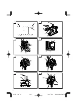
Fig. 4
).
(2)
Retract the protective cover into the saw cover.
(3)
Insert wood chip in the rear side of the saw
blade base, and mark the position on the base
(
Fig. 5
).
(4)
Move the marked wood chip to the front of
the base, and turn the parallelism adjustment
screw so that the marking corresponds to the
base side (
Fig. 6
).
(5)
After adjustment, fasten the mounting screws
tightly in place.
NOTE
䡬
Parallelism may be slightly faulty if the cutting
depth is adjusted after parallelism adjustment.
CUTTING PROCEDURES
1. Place the saw body (base) on the lumber, and align
the marked off line with the saw blade by use of the
front scale. When the saw blade is not inclined, the
right-hand side is the reference (
Fig. 7
).
2. Turn ON the switch before the saw blade contacts the
lumber. The switch is turned ON when the trigger is
squeezed, and turned OFF when the trigger is
released.
3. Moving the saw straight at a constant speed will
produce optimum cutting.
CAUTIONS:
䡬
Before starting to saw, confirm that the saw blade
has attained full-speed revolution.
䡬
Should the saw blade be stopped or made an
abnormal noise while operating, promptly turn OFF
the switch.
䡬
Always take care in preventing the power cord from
coming near to the revolving saw blade.
䡬
Using the Circular Saw with the saw blade facing
upwards or sideways is very hazardous. Such
uncommon applications should be avoided.
䡬
When cutting material, always wear eye protection.
䡬
When finished a job, disconnect the plug from the
receptacle.
MOUNTING AND DISMOUNTING THE SAW
BLADE
CAUTION:
To avoid serious accident, ensure that the switch is in
the OFF position, and the power source is
disconnected.
1. Dismounting the saw blade
(1) Set the cutting depth to maximum and place the
circular saw on a stable place. (
Fig. 8
)
(2) Keeping the lock lever depressed, carefully turn the
hexagonal-head bolt with the box wrench.
(3) When the saw shaft is fixed, turn the wrench
counterclockwise to remove bolt and washer (B).
(4) While gripping the lower guard knob, retract the
lower guard into the saw cover and take out the saw
blade.
2. Mounting the saw blade
(1) Install the saw blade in the reverse order to removal.
(2) Wipe off the swarf from the spindle, washer, etc.
(3) As shown in
Fig. 9
, the side of Washer (A) with a
projected center the same diameter as the inner
diameter of the saw blade and the concave side of
Washer (B) must be fitted to the saw blade sides.
* Washer (A) is supplied for 2 types of saw blades
with the inner diameters of 20 mm and 30 mm.
(When buying the Circular Saw, one type of washer
(A) is supplied.)
In case the inner diameter of your saw blade does
not correspond to that of Washer (A), please contact
the shop where you purchased the Circular Saw.
(4) The saw blade should be installed so that the arrow
in the saw blade is aligned with the arrow on the saw
cover.
(5) Using the fingers, tighten the hexagonal-head bolt
retaining the saw blade as much as possible. Then
depress the lock lever, lock the spindle, and
thoroughly tighten the bolt.
CAUTIONS:
䡬
If a wrench other than the one supplied is used, the
bolt cannot be tightened correctly. Always use the
supplied wrench.
䡬
Before connecting the power plug, check that the
lock lever is returned to its original position and the
saw blade rotates smoothly.
MAINTENANCE AND INSPECTION
1. Inspecting the saw blade
Since use of a dull saw blade will cause motor
malfunctioning and degraded efficiently, replace with
a new one without delay if abrasion is noted.
2. Inspecting the mounting screws
Regularly inspect all mounting screws and ensure
that they are properly tightened. Should any of the
screws be loose, retighten them immediately. Failure
to do so could result in serious hazard.
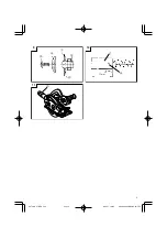
3. Inspecting the carbon brushes (Fig. 10)
The motor employs carbon brushes which are
consumable parts. Since an excessively worn carbon
brush could result in motor trouble, replace the carbon
brushes with new ones which have the same carbon
brush No. shown in the figure when they become
worn to or near the “wear limit”. In addition, always
keep carbon brushes clean and ensure that they slide
freely within the brush holders.
4. Replacing carbon brushes
Disassemble the brush caps with a slotted-head
screwdriver. The carbon brushes can then be easily
removed.
5. Maintenance of the motor
The motor unit winding is the very “heart” of the
power tool. Exercise due care to ensure the winding
does not become damaged and/or wet with oil or
water.
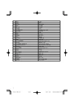
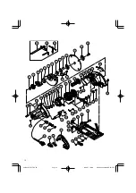
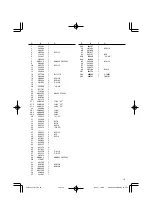
6. Service parts list
A : Item No.
B : Code No.
C : No. Used
D : Remarks
02Eng̲C7MFA̲ChS
09.2.27, 19:06
Page 12
Adobe PageMaker 6.5J/PPC
Содержание C 7MFA
Страница 15: ...14 03Back C7MFA ChS 09 2 27 19 06 Page 14 Adobe PageMaker 6 5J PPC ...
Страница 16: ...15 03Back C7MFA ChS 09 2 27 19 06 Page 15 Adobe PageMaker 6 5J PPC ...
Страница 18: ...17 03Back C7MFA ChS 09 2 27 19 06 Page 17 Adobe PageMaker 6 5J PPC ...
Страница 19: ...18 03Back C7MFA ChS 09 2 27 19 06 Page 18 Adobe PageMaker 6 5J PPC ...


