--- 17 ---
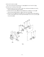
(2) Reassembly of the Gear [1]
(a) Apply grease (Hitachi Motor Grease No. 29) to the pinion and the meshing parts of the Gear [1], and also
to the inside of the metal of Inner Cover (B) [24] (5 grams in total).
(b) When securing Inner Cover (A) Ass'y [20] to Inner Cover (B) [24] with the Nylock Bolt (W/Flange) M4 x 12
[25], be careful not to interfere with the rotation of the pinion.
(3) Checking of operation after reassembly
(a) Check that the Knob [44] operates smoothly and the switch trigger can be locked and released reliably.
Check that the Lamp (12V 5W) [48] is turned on when the knob is operated.
(b) Check that the cutting and inclining operation of the Base Ass'y [63] is smoothly performed.
(c) Check that the Safety Cover [4] operates smoothly.
(d) Check that the brake is applied when turning off the switch.
(e) Check that the saw blade turns in the arrow direction indicated on the saw cover (counterclockwise viewed
from the front of the saw blade).
(f) Check that runout of the saw blade is 0.6 mm or less at 150 mm dia. position.
(4) Wiring Diagram
Perform wiring as illustrated in Fig. 9. Note that wrong wiring can cause troubles such as rotation failure,
inverse rotation and brake failure.
Switch (1P Screw
Type) W/O Lock [41]
Lamp (12V 5W) [48]
Motor (B) [19]
Connector 50092 [47]
Resistor [40]
Red
Brown
Blue
Black
Resistor (A) [38]
Blue
Fig. 9
Connector 50092 [47]
Содержание C 6DC2
Страница 27: ......


