O
I
L
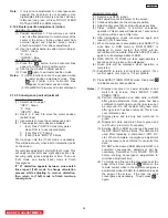
NOTE:
Setting to the center between purple and
crimson is optimum.
OPTICAL FOCUSING ADJUSTMENT RED
(6) In case of B lens. Set the position where the
chromatic aberration changes from purple to
green. As shown below, observe the vertical
bright line and adjust lens focus where the
purple or green chromatic aberration slightly
appears inside and purple or green outside
(reference value : 1~3mm) at the point specified
in table below. Change the signal and fine-
adjust in the same way as the G lens.
O
I
L
NOTE:
Setting the center between Red and crimson
is optimum.
(5) In case of R lens. Set the position where the
chromatic aberration changes from red to
crimson. As shown below, observe the vertical
bright line and adjust lens focus where the
crimson or red chromatic aberration slightly
appears inside, and crimson or red outside
(reference value : 1~3mm) at the point specified
in table below. Change the signal and fine-
adjust the same way as the G lens.
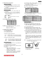
OPTICAL FOCUSING ADJUSTMENT GREEN
Change the signal to the circle pattern and fine
adjust. Observe the corner part of the screen,
especially observe number in the small circle
when adjusting. If the focus performance at the
screen center exceeds the lower limit, it is
acceptable.
Small circle of circle pattern
NOTES: 1.
Since the G light is very important for
picture quality and performance, pay
special attention in its adjustment.
2.
Be careful not to touch the lens with your
fingers when adjusting.
CHASSIS
DP
65/DP65G
SCREEN SIZE
51”
(
D250
)
57”
(
D250
)
L1 and L2
(PITCHES from CENTER)
3
.0
2
.0
BETWEEN
L1&L2
*
*
*
COLOR
*
*
*
ABERRATION I
3
.
0
mm MAX
3
.0mm MAX
*
*
*
O
3
.
0
mm MAX
3
.0mm MAX
(NOTE)
* Slightly reddish or no color
** Slightly bluish or no color
6
5”
(D260)
2
.0
*
*
*
2
.0mm MAX
*
*
2
.0mm MAX
CHASSIS
DP
65/DP65G
SCREEN SIZE
51”(
D250
) 57”(
D250
)
L1 and L2
(PITCHES from CENTER)
5
.0
5
.0
BETWEEN
L1&L2
*
*
*
COLOR
*
*
*
ABERRATION I
3.5
mm MAX
2
.0mm MAX
*
*
*
O
2
.
5
mm MAX
2
.0mm MAX
(NOTE)
* Slightly reddish or no color
** Slightly
crimson
or no color
65”(D260)
4
.0
*
*
2
.0mm MAX
*
2
.0mm MAX
3
7
DP65
Содержание 51F59A
Страница 89: ...CIRCUIT BLOCK DIAGRAM TABLE OF CONTENTS 88 DP65 DP65G ...
Страница 90: ...DP65 DP65G CONNECTION DIAGRAM TABLE OF CONTENTS 89 ...
Страница 94: ...93 DP65 CPT P W B TABLE OF CONTENTS ...
Страница 96: ...TABLE OF CONTENTS FINAL WIRING DIAGRAM TABLE OF CONTENTS TABLE OF CONTENTS DP65 95 ...
Страница 97: ...TABLE OF CONTENTS FINAL WIRING DIAGRAM TABLE OF CONTENTS TABLE OF CONTENTS DP65 96 ...
Страница 100: ...TABLE OF CONTENTS TABLE OF CONTENTS TABLE OF CONTENTS FINAL WIRING DIAGRAM TABLE OF CONTENTS TABLE OF CONTENTS DP65 99 ...
Страница 101: ...TABLE OF CONTENTS TABLE OF CONTENTS TABLE OF CONTENTS FINAL WIRING DIAGRAM TABLE OF CONTENTS TABLE OF CONTENTS DP65 100 ...
Страница 110: ...109 SCREEN FRAME ASSY 4 65F59 A Top Frame P TBD Vertical frame P TBD Bottom frame P TBD ScreenAssy 65F59 A P TBD ...
Страница 151: ...BACK TO TABLE OF CONTENTS PRINTED CIRCUIT BOARDS DP65 POWER DEFLECTION PWB Solder side DP65 150 ...
Страница 154: ...BACK TO TABLE OF CONTENTS PRINTED CIRCUIT BOARDS DP65 CPT PWB Solder side DP65 153 ...
Страница 183: ......


