23
PT5-G/PW1-H
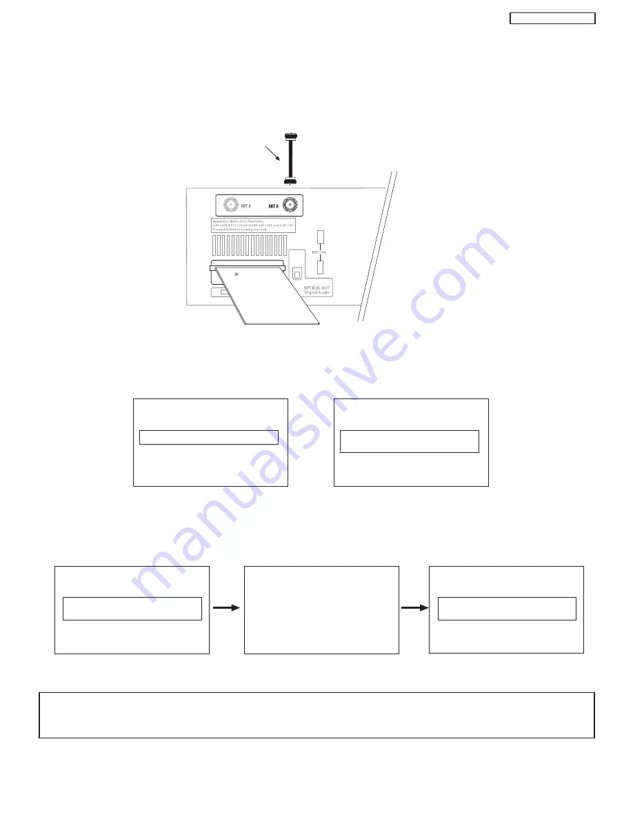
CONNECTING AV NETWORK
INSER
T
THIS END
CableCARD
Digital Cable
After the CableCARD is installed, wait until the second screen below appears. The third screen below will appear if a channel is not
authorized for viewing. Press the EXIT button to exit the second screen.
Please take note of all information on the screen (you will provide this information to your cable operator). Call your cable operator
and give them the information from the card to start your cable service.
s
CableCARD Slot
This slot is for the CableCARD that will be provided by your local cable operator to gain access to chosen cable channels. The
CableCARD will allow you to tune digital and high definition cable channels. Please call your local cable operator if this service is
available before requesting a CableCARD (also known as Point of Deployment (POD) module).
Connect a coaxial cable to ANT A terminal of the Rear Panel Jacks.
Insert the CableCARD into the slot (Top of card should be facing up as shown).
Rear Panel of AVC
If the CableCARD is properly installed or not installed, the TV will display the following respective screens.
CableCARD is installed
CableCARD
is not installed
OR
In order to start cable service
for this device, please contact
your cable provider
CableCARD(tm): 123-456-789-1
Host: 123-456-789-1
Data: 123-456-789-1
UnitAddress: 123-456-789-1
Acquiring Data.
Please wait.
Press EXIT to return
Not an Authorized Channel
NOTES:
1.
A digital cable subscription is required.
2.
Antenna B will not be available when CableCARD is inserted.
3.
Do not insert a PCMCIA card into the CableCARD slot.
Содержание 42HDT51M
Страница 12: ...12 PT5 G PW1 H TABLE OF CONTENTS Specification Features A Plasma ...
Страница 13: ...13 PT5 G PW1 H ...
Страница 14: ...14 PT5 G PW1 H B Environment ...
Страница 15: ...15 PT5 G PW1 H ...
Страница 16: ...16 PT5 G PW1 H ...
Страница 30: ...30 PT5 G PW1 H 5 7 WHITE BALANCE ADJUSTMENT OSD FLOW DIAGRAM BACK TO ADJUSTMENTS ...
Страница 32: ...32 PT5 G PW1 H 9 SETTING for Delivery ...
Страница 33: ...33 PT5 G PW1 H 9 SETTING for Delivery continued ...
Страница 34: ...34 PT5 G PW1 H 9 SETTING for Delivery continued ...
Страница 35: ...35 PT5 G PW1 H 9 SETTING for Delivery continued ...
Страница 36: ...36 PT5 G PW1 H 9 SETTING for Delivery continued ...
Страница 53: ...53 PT5 G PW1 H 12 Circuit Block Diagram MONITOR ...
Страница 54: ...54 PT5 G PW1 H MONITOR ...
Страница 55: ...55 PT5 G PW1 H 12 Power Circuit Block Diagram MONITOR ...
Страница 56: ...56 PT5 G PW1 H MONITOR ...
Страница 57: ...57 PT5 G PW1 H 12 2 MPU Control Block Diagram MONITOR ...
Страница 58: ...58 PT5 G PW1 H MONITOR ...
Страница 64: ...FINAL WIRING DIAGRAM MONITOR 64 PT5 G PW1 H ...
Страница 65: ...FINAL WIRING DIAGRAM MONITOR 65 PT5 G PW1 H ...
Страница 66: ...FINAL WIRING DIAGRAM MONITOR 66 PT5 G PW1 H ...
Страница 67: ...FINAL WIRING DIAGRAM MONITOR 67 PT5 G PW1 H ...
Страница 95: ...AVC5U 95 PRINTED CIRCUIT BOARDS AV P W B CS TABLE OF CONTENTS ...
Страница 96: ...96 AVC5U PRINTED CIRCUIT BOARDS AV P W B SS TABLE OF CONTENTS ...
Страница 97: ...97 AVC5U PRINTED CIRCUIT BOARDS CONTROL P W B TABLE OF CONTENTS ...
Страница 98: ...98 AVC5U PRINTED CIRCUIT BOARDS HDMI P W B CS TABLE OF CONTENTS ...
Страница 99: ...99 AVC5U PRINTED CIRCUIT BOARDS HDMI P W B SS TABLE OF CONTENTS ...
Страница 100: ...100 AVC5U PRINTED CIRCUIT BOARDS SW P W B SS TABLE OF CONTENTS ...
Страница 101: ...101 PT5 G PRINTED CIRCUIT BOARDS FILTER P W B CS TABLE OF CONTENTS ...
Страница 102: ...102 PT5 G PRINTED CIRCUIT BOARDS FILTER P W B SS TABLE OF CONTENTS ...
Страница 103: ...103 PT5 G PRINTED CIRCUIT BOARDS LED P W B TABLE OF CONTENTS ...
Страница 104: ...104 PT5 G PRINTED CIRCUIT BOARDS SIGNAL AUDIO P W B CS TABLE OF CONTENTS ...
Страница 105: ...105 PT5 G PRINTED CIRCUIT BOARDS SIGNAL AUDIO P W B SS TABLE OF CONTENTS ...
Страница 106: ...106 PT5 G PRINTED CIRCUIT BOARDS SW P W B TABLE OF CONTENTS ...
Страница 107: ...107 PT5 G PW1 H ...
Страница 108: ...108 PT5 G PW1 H ...
Страница 131: ......


