background image

1

6

28LD5200E (PW1L) 

Item 

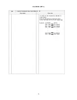
AUTOMATIC SIGNAL LEVEL ADJ USTMENT –RGB (1) 

Preparation       

Procedure 

(1)  Input the adjustment signal of VGA (60Hz) 

format into RGB2 [D-sub] input terminal. 
 

(1) Select RGB2 and enter the service adjustment 

mode. 

 the 

adjustment 

signal 


(2) Select No.740 “RGB Amp. Gain ADJ.” and press 

OK button for more than 2 seconds to start the 
adjustment. 
It will complete the adjustment after the OSD of 
“AUTO MODE” disappeared. 

[Note] Never adjust without use of the specified signal. 

If that were done by mistake, the picture would become abnormal in black level, contrast and color. 
In this case, it will be recovered by re-adjustment in the specified way. 

Item 

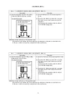
AUTOMATIC SIGNAL LEVEL ADJ USTMENT –RGB (2) 

Preparation       

Procedure 

(1)  Input the adjustment signal of 576p or 480p 

format into AV1 input terminal. 

(1) Select AV1 and enter the service adjustment mode.

  the adjustment signal 

(2) Select No.740 “RGB Amp. Gain ADJ.” and press 

OK button for more than 2 seconds to start the 
adjustment. 
It will complete the adjustment after the OSD of 
“AUTO MODE” disappeared. 


(3) Select No.741 “RGB Amp. Gain ADJ.” and press 

OK button for more than 2 seconds to start the 
adjustment. 
It will complete the adjustment after the OSD of 
“AUTO MODE” disappeared.   


[Note] Never adjust without use of the specified signal. 

If that were done by mistake, the picture would become abnormal in black level, contrast and color. 
In this case, it will be recovered by re-adjustment in the specified way. 

The signal level of black area 
should be pedestal level. 
This signal must not be inserted 
characters etc. 

Black  White 

0.7V 

The signal level of black area 
should be pedestal level. 
This signal must not be inserted 
characters etc. 

Black  White 

0.7V 
Содержание 28LD5200E

Страница 1: ...nction 22 7 Replacement parts list 23 8 Block diagram 24 9 Connection diagram 26 10 Wiring diagram 27 11 Disassembly diagram 28 Contents 1 Since Panel Module is made of glass handling the broken Module shall be taken care sufficiently in order not to be injured 2 Replacing work shall be started after the Panel Module and the AC DC Power supply become sufficiently cool 3 Special care shall be taken...

Страница 2: ...s You could die or suffer from electric shock if you touch live part Use recommended components Please use same characteristic compo nent which is same as original for your safety and reliability Especially those marked by in parts list and circuit dia gram It may cause electric shock or fire if you use non recommended component Should keep same style of wiring or component Monitor uses tubes or t...

Страница 3: ... color misconvergence and display distortion High Performance Digital Processor A wide range of personal computer signals can be handled from 640 x 400 640 x 480 VGA to 1600 x 1200 UXGA RGB Analog input Easy to use remote control and on screen display system The remote control included eases the work of setting display controls Further the on screen display system displays the status of signal rec...

Страница 4: ... video input terminal RCA AV1 Y PB PR video input terminal RCA AV1 L R audio input terminal RCA AV2 composite video input terminal RCA AV2 Y G PB B PR R video input terminal RCA AV2 L R audio input terminal RCA AV3 composite video input terminal RCA AV3 S video input terminal RCA AV3 L R audio input terminal RCA AV4 composite video S video RGB L R audio input terminal Scart Video signals AV1 PAL S...

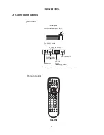
Страница 5: ...tton INPUT SELECT button OK button PROGRAM UP button SELECT button These buttons are located on the top SUB POWER button Control panel VOLUME UP DOWN buttons ADJUST buttons MENU button indicates the function while the MENU is displayed on the screen Remote Control Main unit ...

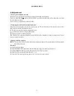
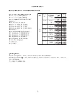
Страница 6: ...cting adjustment code buttons are used for changing data values OK button is used for confirming the data After finishing the necessary adjustment press MENU button Adjustment mode is released and the set returns to normal condition Memory Initialize operation NOTE The execution of this function returns the adjustment codes to the preset values therefore adjust ment data will be lost Procedure 1 E...

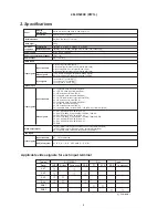
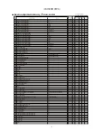
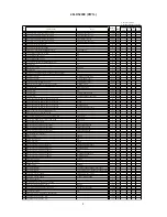
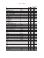
Страница 7: ...34 SUB_COLOR VIDEO PAL SECAM MAIN 15 0 35 SUB_COLOR RF PAL SECAM MAIN 15 3 36 SUB_COLOR VIDEO NTSC MAIN 15 0 37 SUB_COLOR RF NTSC MAIN 15 11 38 SUB_COLOR VIDEO PAL SECAM SUB 15 0 39 SUB_COLOR RF PAL SECAM SUB 15 3 40 SUB_COLOR VIDEO NTSC SUB 15 0 41 SUB_COLOR RF NTSC SUB 15 11 42 TINT VIDEO MAIN 63 33 O 43 TINT RF MAIN 63 33 O 44 TINT VIDEO SUB 63 33 O 45 TINT RF SUB 63 33 O 46 S_B Y_ADJ MAIN 15 8...

Страница 8: ...1 147 CNRINV 1 0 148 CNRLIM 3 1 149 YPFG 15 8 150 SEPA_LEVEL 480i 576i 3 2 151 SEPA_LEVEL 480p 576p 3 2 152 SEPA_LEVEL 1080i_50 3 2 153 SEPA_LEVEL 1080i_60 720p 3 2 154 AUTO_FM AM D11 D8 15 2 155 AUTO_FM AM D7 D0 254 189 156 A2_THRESHOLD D11 D8 15 0 157 A2_THRESHOLD D7 D0 254 112 158 PRE_AM Except 4 5MHz Except Dual Stereo mode 254 17 159 VOL_SCART1 D15 D8 254 115 160 VOL_SCART1 D7 D5 7 0 161 PRE_...

Страница 9: ... HD10 31 10 230 Center of Sharpness HV Enhancer Gain for Y For Europe NT2 NT3 PAL2 PAL3 NT4 PAL4 31 14 231 Center of Sharpness HV Enhancer Gain for Y For Europe TEXT for split 31 7 232 Maximum Value of Contrast at REAL NORMAL mode 254 188 233 Offset Value of Contrast data at SPLIT mode 120 55 234 Offset value of gain for Black Stretch function Except OFF LOW HIGH mode 63 33 235 Demonstration White...

Страница 10: ... software OSD change Wide Mode 0 For Europe 1 Foe USA DAY NIGHT 1 0 321 Count Souce for ON OFF Timer 0 MCU 250ms 1 AC 50 60Hz 1 0 322 Select Wide mode for Europe model Normal 5mode For Service 10 mode 0 Normal 1 For service 1 0 323 Forced AVC type available 0 Normal type 1 Forced AVC type 1 0 324 Sharpness Gain Main M PAL 15 8 325 Sharpness f0 Main M PAL 3 2 326 Sharpness Gain Sub M PAL 15 9 327 S...

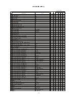
Страница 11: ...26 Horizontal Coring Level Enhancer Gain EU HECORE_PO PAL1 RF multi 15 1 427 Vertical Coring Level Enhancer Gain AS VECOR0_PO NT1 RF 15 1 428 Vertical Coring Level Enhancer Gain AS VECOR1_PO PAL1 RF multi 15 1 429 Vertical Coring Level Enhancer Gain VECOR2_PO NT1 Video 15 1 430 Vertical Coring Level Enhancer Gain VECOR3_PO PAL1 Video 15 1 431 Vertical Coring Level Enhancer Gain VECOR4_PO NT2 NT3 N...

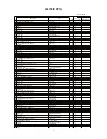
Страница 12: ..._P0 NTSC PAL multi 63 0 513 YHNLP1_P0 HD 63 0 514 Coring Amplitude for Y G YCOR0_PO NT1 RF PAL1 RF multi 7 7 515 YCOR1_PO NT1 Video PAL1 Video 7 5 516 YCOR2_PO NT2 NT3 NT4 PAL2 PAL3 PAL4 7 3 517 YCOR3_PO HD2 HD3 HD9 HD10 7 1 518 YCOR4_PO HD1 HD4 HD5 HD6 HD7 HD8 7 1 519 Vertical Enhancer Gain for Y G YVEG0_P1 NTSC PAL RFએᄖ 15 15 520 YVEG1_P1 HD2 HD3 HD9 HD10 15 4 521 YVEG2_P1 HD1 HD4 HD5 HD6 HD7 HD...

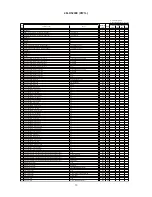
Страница 13: ...5 For Europe Main 63 16 606 Y OUT LEVEL I 6 0 For Europe Main 63 19 607 Y OUT LEVEL L 6 5 For Europe Main 63 13 608 Y OUT LEVEL L 6 1 For Europe Main 63 12 609 Y OUT LEVEL M 4 5 For US Main 63 13 610 C OUT LEVEL M 4 5 For Asia Main 63 7 611 C OUT LEVEL B G 5 5 For Asia Main 63 13 612 C OUT LEVEL D K 6 5 For Asia Main 63 13 613 C OUT LEVEL I 6 0 For Asia Main 63 13 614 C OUT LEVEL B G 5 5 For Europ...

Страница 14: ...in for Y For Asia US HD1 HD4 HD7 HD8 31 10 692 Center of Sharpness HV Enhancer Gain for Y For Asia US HD2 HD3 HD9 HD10 31 10 693 Center of Sharpness HV Enhancer Gain for Y For Asia US NT2 NT3 PAL2 PAL3 NT4 PAL4 31 14 694 Center of Sharpness HV Enhancer Gain for Y For Asia US TEXT 2pictures 31 15 695 Contrast mode Dynamic SW TV 0 Dynamic 1 Dynamic Auto TV 1 1 696 V detection FORMATTER PWB 0 out of ...

Страница 15: ...Component TV NTSC HD PC PC signal Video Input System Judgment of H Frequency Video Input Setup Mode AV1 AV2 PAL 15 75kHz 576i Auto PAL2 SDTV DVD PAL2 HDTV PAL3 NTSC 15 75kHz 480i Auto NT2 SDTV DVD NT2 HDTV NT3 PAL 31 25kHz 576p Auto HD10 SDTV DVD HD10 HDTV HD9 NTSC 31 50kHz 480p Auto HD3 SDTV DVD HD3 HDTV HD2 NTSC 45 00kHz 720p Auto HD5 SDTV DVD HD6 HDTV HD5 PAL 28 125kHz 1080i Auto HD7 SDTV DVD H...

Страница 16: ...al of 576p or 480p format into AV1 input terminal 1 Select AV1 and enter the service adjustment mode the adjustment signal 2 Select No 740 RGB Amp Gain ADJ and press OK button for more than 2 seconds to start the adjustment It will complete the adjustment after the OSD of AUTO MODE disappeared 3 Select No 741 RGB Amp Gain ADJ and press OK button for more than 2 seconds to start the adjustment It w...

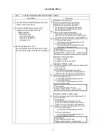
Страница 17: ... Set the Picture mode of Picture menu Dynamic 4 Adjustment of Warm mode Enter the service adjustment mode and confirm that Adjustment NO 6 7 and 8 are all set as 230 In factory setting mode No 8 B drive warm will be adjusted decrease from 230 until one of x y is in spec and another value is higher than spec When both x and y are in spec value it is end of adjustment According to x and y value the ...

Страница 18: ...e It is same as color temperature adjustment data of video Write the data which are inside drive No0 to No11 into drive N0 12 to No 23 respectively Example at VIDEO at PC No 0 data No 12 data No 1 data No 13 data No 2 data No 14 data No 10 data No 22 data No 11 data No 23 data ...

Страница 19: ...and the OSD of BURN IN ON To escape from this mode press the SUB POWER button INPUT SELECT button and button at the same time and hold for more than 5 seconds Burn in mode will be released How to recover the remote and front key function If remote and front key cannot operate after miss set special function by front keys these functions can recover by below method Press the SUB POWER button INPUT ...

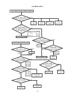
Страница 20: ... unit CN5 1 3 Is the voltage applied to P804 3 pin of Power supply unit high AC inlet Power switch Are the voltages applied to P804 1 8 pins P806 1 pin and P808 1 4 8 12 pins of Power supply unit 1 5V 8 6V 1 12V P804 P804 3 Power GO P804 5 Power OFF P806 P808 1 30V 4 5V 8 12V 12 10V Joint Formatter PWB Power supply unit No Yes Joint Formatter PWB Power supply unit Yes high Yes high Sub Power board...

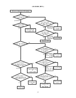
Страница 21: ...gnal Cable or Formatter PWB Yes No Inverter unit No Yes 1 5V 3 5V Is Voltage applied to P804 1 pin of the Power supply unit Is Voltage applied to EJF1 3 pin of the Joint PWB Power supply unit No Yes Joint PWB Formatter PWB Power supply unit Power supply unit or Formatter PWB Power supply unit No Yes Formatter PWB or Panel Module Is the voltage of EFJ1 1 pin EFJ2 1 2 pins applied to of the Formatte...

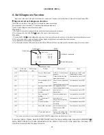
Страница 22: ...se OSD of Check Antenna appears No connection of ANT cable Preset tuning is not yet H11 Tuner problem Cannot receive the main signal from antenna Communication error of U101 H15 Composite video SW IC problem Cannot receive picture and audio Cannot change input mode Communication error of I201 H16 Component video SW IC problem No component picture Cannot change input mode Communication error of I20...

Страница 23: ...THE UPDATED PARTS LIST FOR THIS MODEL IS AVAILABLE ON ESTA 23 ...

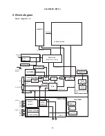
Страница 24: ...al Audio Amp Noise Filter LVDS Transmitter Power Unit Main Power Circuit DVI Signal Power Audio Power Supply FC4 CPU Sub D SUB15P VIDEO PWB TACT SW PWB AUDIO SELECT AUDIO AV1 AV1 AV2 AV3 AV4 AV2 AV3 AV4 VIDEO VIDEO CROMA 3D 3L COMB VIDEO SELECT Tuner PWB Tuner FE TELE TEXT VIDEO OUT Digital RGB Differential signal LCD Panel Module DAC INVERTER Inverter Power Back light 8 Block diagram Block diagra...

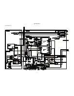
Страница 25: ...25 28LD5200E PW1L Block diagram 2 2 ...

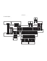
Страница 26: ...S RESET AVC PARITY AVDET2 AVC RXD 31 32 33 34 35 36 37 38 39 40 AVC RXD 71 72 73 74 75 5V MD2 76 77 78 79 80 RES FEW FCK REM PDP AVC TXD PDDET S TXD S RXD 51 52 53 54 55 56 57 58 59 60 41 42 43 44 45 46 47 48 49 50 51 52 53 54 55 56 57 58 59 60 61 62 63 64 65 66 67 68 69 70 71 72 73 74 75 76 77 78 79 80 31 32 33 RXD 34 35 36 37 38 39 Vpp BUSY TXD SCLK CNVSS RESET AVC PARITY AVDET2 71 72 73 74 75 5...

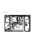
Страница 27: ...LED board POWER SW INLET board SUB POWER board ECONT EJA1 EJF2 CN4 CN5 SW902 CN5 1 CN6 1 CN1 EAF1 EJP1 EJF4 EJF6 EJF5 EJF3A EFJ3 EFJ2 EFJ1 EFP1 EFP2 EFJ4 EFA1 EFL1 EFK1 EFG1 EFG2 EPM1 EJP2 P802 P803 P804 P806 P808 P804 CN6 EAJ1 To Panel CN2 CN4 1 SW901 86 86 34 31 33 86 21 22 25 37 86 38 30 24 23 27 26 29 32 10 Wiring diagram ...

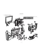
Страница 28: ... in brackets shown in the wiring diagram express the name of materials The key to the codes and materials is shown on the table below Code ABS PC Material ACRYLONITRILE BUTADIENE STYRENE POLYCARBONATE 5 2 5 11 Disassembly diagram ...

Страница 29: ...47 Milano Italia ITALY Tel 39 02 487861 Tel 39 02 38073415 Servizio Clienti Fax 39 02 48786381 2 Email customerservice italy hitachi eu com HITACHI Europe AB Box 77 S 164 94 Kista SWEDEN Tel 46 0 8 562 711 00 Fax 46 0 8 562 711 13 Email csgswe hitachi eu com HITACHI EUROPE S A S Lyon Office B P 45 69671 BRON CEDEX FRANCE Tel 04 72 14 29 70 Fax 04 72 14 29 99 Email france consommateur hitachi eu co...

Отзывы: