- 5 -
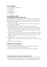
TEST EQUIPMENT
1) DC regulated power supply PAB18-1.8
2) Audio voltameter
3) Oscilloscope
4) High-voltage meter
5) Digital multimeter
6) AC voltameter
TEST MODE SET(CHECK)
TEST MODE ADJUSTMENT INSTRUCTION
TEST MODE adjustment is a special adjustment which is controlled by I
2
C BUS. The TV set has
been set at optimum mode at the factory. Except for special need, such as replacing CRT
、
MEMORY
、
IC etc., it is hoped not to adjust it. To conduct TEST MODE's adjustment, please do it
according to the following steps:
There are two special romote controller for the set. One is "Under Adjustment" and the other is
"Under Adjustment for W/B Balance".
1) Press "PROD" button to enter the FACTORY, B/W BALANCE, ADJUST or SETUP mode.
2) In B/W BALANCE mode, select the item you want to adjust directly by pressing the button on
the"Under Adjustment for W/B Balance" remote controller and use the "ADJ+" or "ADJ-" button
to adjust. You can press "ADJUP" or "ADJDOWN" to select needed adjustment item and use
the "ADJ+" or "ADJ-" button to adjust too.
3) In ADJUST mode, select the item you want to adjust directly by pressing the button on the "Under
Adjustment" remote controller and use the "ADJ+" or "ADJ-" button to adjust. You can press
"ADJUP" or "ADJDOWN" to select needed adjustment item and use the "ADJ+" or "ADJ-"
button to adjust too.
4) In SETUP mode, select the item you want to adjust by pressing the button "ADJUP" or
"ADJDOWN" on the "Under Adjustment". Then use the "ADJ+" or "ADJ-" button to adjust.
adjust.
5) Press "PROD" to exit the TEST MODE.
H-blanking, H-center adjustment
1) Receive test signal, enter into the ADJUST mode.
2) Select the H.BLK.LEFT and H.BLK.RIGHT item, adjust the level to make the H -blanking
amount on the left and right screen at an appropriate position.
3) Select the H.PHASE item, adjust the level to make the left and right picture sysmmetrical.
V-amplitude, linearity, S-correction, center adjustment
1) Receive test signal, enter into the ADJUST mode. adjust the value to make V-center and the CRT's
2) Select the V.POS item , adjust the value to make V-center and the CRT's geometric center is in
accordance. Then select the V.SIZE item, adjust the value to make the overscan is less than or
Содержание TC14FS68
Страница 13: ... 12 ...
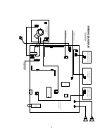
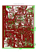
Страница 17: ...COMPONENT VIEW OF MAIN BORAD 16 ...
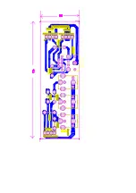
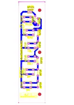
Страница 18: ......
Страница 19: ......
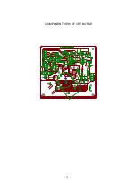
Страница 20: ...COMPONENT VIEW OF CRT BORAD 18 ...
Страница 21: ...COMPONENT VIEW OF STEREO BORAD 20 ...
Страница 33: ...NO DESCRIPTION UNIT QTY LOCATION Page 11 of 22 ...


