background image


14 

Start-up:  When  the  adapter  is  connected,  hold  down  the  switch  button  on  the  right  back  side  of  the 

bottom of the machine for about 3 seconds. When the screen is on and the button indicator light is on, the 
startup can be realized. 

Shutdown:  Press  the  switch  button  on  the  right  back  side  of  the  bottom  of  the  machine  for  about  3 

seconds, and operate according to the screen prompt, which can realize shutdown and restart functions. 

3)


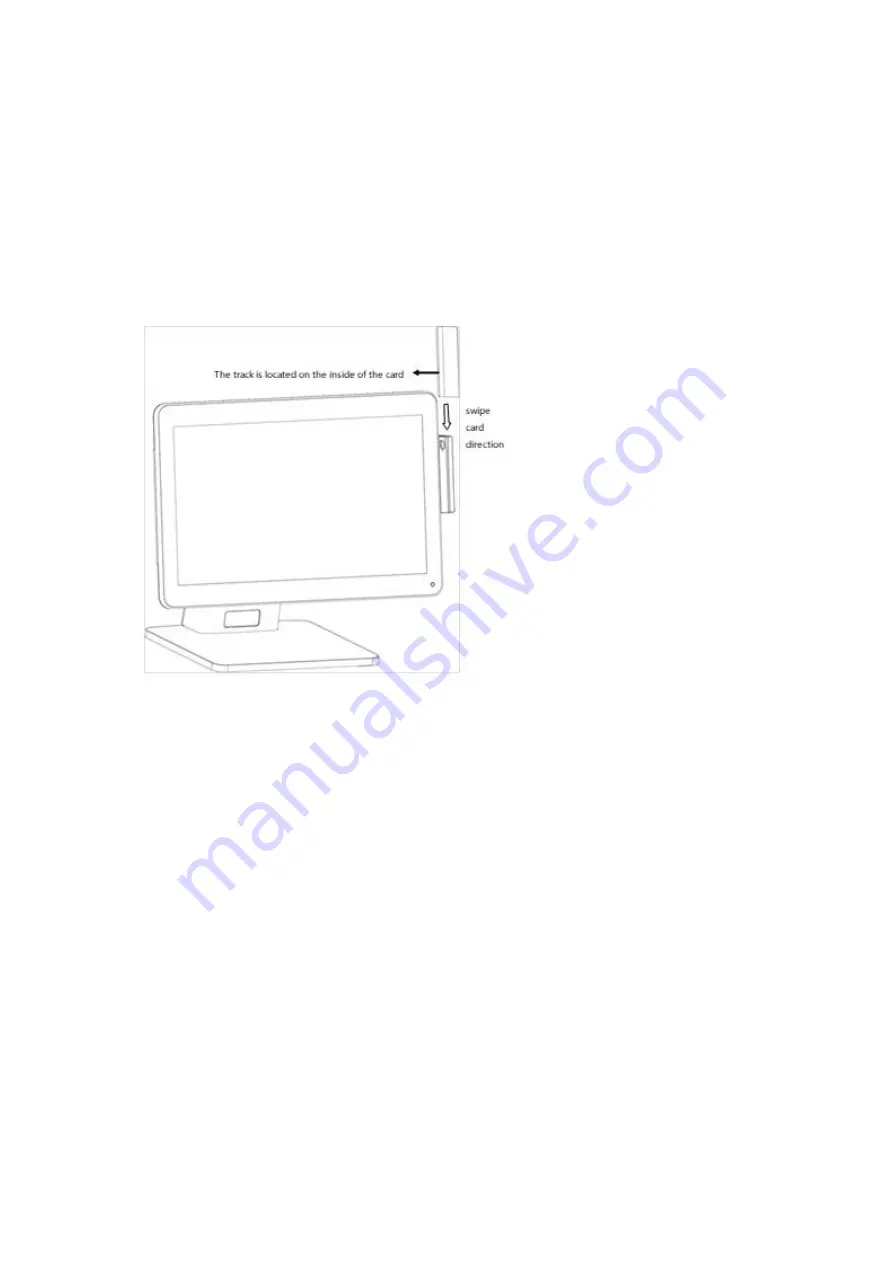
Swipe magnetic cards


When swiping the card, the machine should be placed on a hard horizontal plane. 


Please swipe the magnetic strip of the magnetic strip card inward from the swipe slot. 


The process of card swiping should be smooth and uniform. 


4)


Contactless card operation


Contactless card induction zone is located behind the right side of the host (with the contactless mark 
printed). 

When need read contactless card, please place the card above the induction zone.


9.


Printer operations


1)


Printer Structure 

Содержание HK316

Страница 1: ...1 HK316 User s Manual Document version 1 3 ...

Страница 2: ...nd leakage and other faults you must switch off the power supply at once and then contact with reseller When inserting USB flash or disk you shall kill virus to prevent the host machine from virus The RJ11 port at the back of the host is connected with the cash drawer as it is not a communication port users shall not use the port for dial up networking The product is a Level A one it may cause rad...

Страница 3: ...n Item Description Model HK316 System CPU Cortex A17 Quad core CPU clock speed 1 8GHz Memory 2G Storage Flash Memory eMMC 16GB Nand Flash LCD Touch Panel LCD Size 15 6 inch Resolution 1920 1080 Touch Screen capacitive true flat touch I O Ports Serial Ports 1 RJ48 COM COM1 USB 5 USB 2 0 4 on IO panel 1 under side cover Micro USB 1 under side cover for debug only TF card 1 under side cover LAN 1 RJ ...

Страница 4: ... 13 14 15 16 1 24V power input 2 Cash drawer interface 3 Serial port 4 printer 24V power 5 USB 2 6 USB 2 7 RJ45 8 Audio 9 Volume button 10 Volume button 11 Brightness button 12 Brightness button 13 TF card slot 14 Micro USB 15 USB ...

Страница 5: ...x2set 6 CON5 12V power input 7 CON19 24V power output 8 J10 1 3 wafer2 0 jumpersx1set 9 CON31 MIC pin wafer2 0 1 2 pinx1set MIC 10 CON18 Speaker pin wafer2 0 1 4 pinx1set SPEAKER 11 CON61 Serial port 40PIN FPC socket Expansion board 12 CON58 Speaker pin wafer2 0 1 4 pinx1set Reserved SPEAKR 13 CON7 Serial port wafer1 25 1 5pinx1set Reserved USB 14 CON8 Edp zero lift drag 40 pinx1set Edp2 secondary...

Страница 6: ... 21 GND 2 GND 22 Enable 3 Lane1_N 23 PWM 4 Lane1_P 24 NC 5 GND 25 NC 6 Lane0_N 26 PWR 7 Lane0_N 27 PWR 8 GND 28 PWR 9 AUX_CH_P 29 PWR 10 AUX_CH_N 30 NC 11 GND 31 GND 12 VCC 32 GND 13 VCC 33 NC 14 NC 34 NC 15 GND 35 GND 16 GND 36 INT 17 HPD 37 RST 18 GND 38 SCL 19 GND 39 SDA 20 GND 40 VCC ...

Страница 7: ...CC 33 NC 14 NC 34 NC 15 GND 35 GND 16 GND 36 INT 17 HPD 37 RST 18 GND 38 SCL 19 GND 39 SDA 20 GND 40 VCC Audio interface definition Audio Description Audio Code ES8388 Rear IO Type HP Connector Onboard audio pin PIN defined 1 SPK_LP 2 SPK_LN 1 2 3 4 3 SPK_RP 4 SPK_RN PIN Type 1 4Pin 2 0mm wafer box Jumper definition Jumper Pin Function Setting J8 J9 3 pin COM0 COM2 Power Select 1 2 5V 2 3 12V 1 2 ...

Страница 8: ...shell of the base 3 Remove the two connectors shown in the picture and protect them with the tape according to the picture shows to prevent the connector from being pulled out in the process of dismantling and threading for device with OLED customer display can directly pull out the OLED customer display line 4 Rotate the main screen and the secondary screen to the vertical angle remove the three ...

Страница 9: ... host Remove four screws according to the picture shows Remove the hinges of the host and the hinges cover of the host separately 6 Remove the extended interface cover pull the expanded interface cover outward at the notch according to the picture shows and remove it 7 Remove the rear case of the host pull up the rear cover of the host according to the picture shows and remove the rear cover of th...

Страница 10: ...maintained 5 Functional testing and parameter setting of peripherals In product test mode magnetic stripe card test items are swiped by magnetic stripe card and magnetic stripe card corresponding to the track shows success three tracks different magnetic stripe cards may store info into different tracks As the following figure ...

Страница 11: ... show find card Contactless card is divided into A card B card M card As The following figure Printer U port printer without setting baud rate can use the normal detection of product test procedures Cash drawer As shown below for the item CashBox ByCPU in the product test click Click to Open Cashbox ...

Страница 12: ...ironmental requirements Type State Environmental Voltage AC 100V 240V 50 60Hz Bipolar grounding Temperature 5 40 Optimal 40 90 7 Size specification Single screen Length Width Height 405 210 330 Flip Angle 0 45 ...

Страница 13: ... Length Width Height 405 250 420 Self service Length Width Height 230 250 450 8 Open the box and check 1 Before opening the box check whether the box is in good condition and whether there is any obvious damage 2 The equipment must be installed by technical service person or distributors Operation 1 Switching Instructions ...

Страница 14: ...creen prompt which can realize shutdown and restart functions 3 Swipe magnetic cards When swiping the card the machine should be placed on a hard horizontal plane Please swipe the magnetic strip of the magnetic strip card inward from the swipe slot The process of card swiping should be smooth and uniform 4 Contactless card operation Contactless card induction zone is located behind the right side ...

Страница 15: ...tion a Press the open button to open the paper bin cover as shown below If there are paper tubes in the paper warehouse please take them out b Put the paper roll into the paper bin pay attention to the correct direction of the paper roll ...

Страница 16: ... a small amount of paper from the front of the roll and close the cover of the printer s paper bin d Remove excess paper toward the side of the paper cut Paper rolling 1 Requirements of the thermal paper Type Thermal paper ...

Страница 17: ...nting unit the print head should be cleaned A Printing is not clear B The vertical column of the printed page is not clear C Noise of feeding and returning paper is high The cleaning steps of the printing head and Printer rubber roller are as follows A Turn off the power supply of the printing unit open the printer cover and expose the printer head and Printer rubber roller B If you have just fini...

Страница 18: ...d to provide reasonable protection against harmful interference in a residential installation This equipment generates uses and can radiate radio frequency energy and if not installed and used in accordance with the instructions may cause harmful interference to radio communications However there is no guarantee that interference will not occur in a particular installation If this equipment does c...

Отзывы: