Rear-Mounted USB KVM Extender Instructions (continued)
99140B
•
January 6, 2015
•
www.HopeIndustrial.com
•
International:
+1 (678) 762-9790
• UK:
+44 (0) 20 7193 2618
•
© 2015 Hope Industrial Systems, Inc.
•
Page 2 of 2
inlet. Retighten the retaining clip to secure the monitor power cable.
b. For DC powered monitors: Route the monitor power cable through the KVM Remote Module to the monitor, then insert it into the power
inlet. Secure the monitor power cable to the DC power inlet with a Phillips head screwdriver.
9. For touch screen units, connect the USB cable from the KVM Remote Module to the monitor's touch screen port. A cable retention bracket
comes installed on the USB port on the monitor and will help to secure the cable and ensure adequate strain relief. Without removing the
retention bracket, route the USB cable through the end of the bracket and into the USB input port on the monitor. Continue to step 11.
10. For non-touch screen units, ensure the touch USB cable is positioned safely away from any internal components in the monitor cable well.
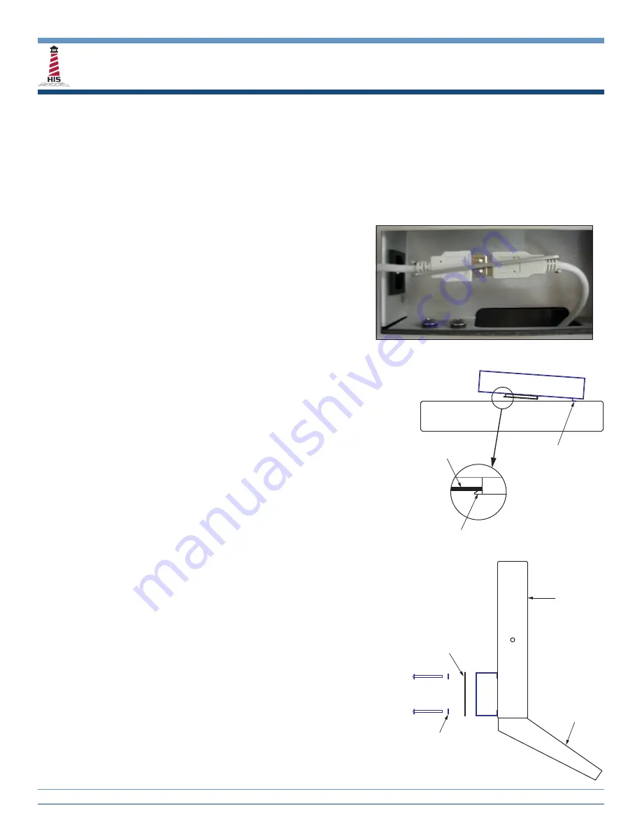
11. For monitors with a permanently installed keyboard, connect the USB cable from the keyboard to the unused USB extension cable on the
KVM Remote Module. Secure the USB connectors with the provided wire retaining clip as shown in the figure below.
NOTE: This KVM is a USB 1.1 device that has been tested to operate
with all Hope Industrial Systems keyboards, mice, and touch screen
monitors to a maximum distance of 60 meters (198'). The maximum
rated power output at the Remote Module is 300mA. Therefore, this
KVM Extender will work with any combination of one keyboard, one
mouse, and one touch screen monitor. Different devices can be
connected as long as the total power requirement does not exceed
the rated power output of 300mA. A 25' shielded CAT5 cable has been
provided for bench testing purposes. When connecting any non-Hope
Industrial devices, it is recommended that the device be fully tested
with the actual cable and length that will be used in service.
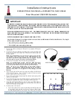
12. Insert the KVM Remote Module into the opening of the rear panel by sliding
the right hand locking tabs in all the way to the right.
13. Press down firmly and slide the KVM Remote Module to the left until it stops with
both left hand locking tabs securely inside the rear panel.
14. Install the CATx cables from the USB and VGA Local Modules into the correctly
labeled inlets on the KVM Remote Module.
15. At this time, check for proper operation of the KVM Extender:
a. Turn on or reboot computer.
b. If extending USB, the USB Power LED on the Remote Module should be lit
green.
c. The VGA CATx inlet on the Remote Module should be lit green.
d. The VGA Local Module should have a green and yellow LED lit (green
represents data and yellow represents power).
e. Check the image on the remote monitor to see if it is being displayed
properly. If necessary, adjust the Sharpness adjustment screw on the KVM
Remote Module to achieve the best possible image.
NOTE ON RESOLUTION DATA: Resolution information is not
transmitted from the remote monitor when using this KVM Extender.
Instead, the local unit holds a standard set of resolutions, which are
suitable for most monitors. If the standard resolutions are not suitable,
temporarily connect the VGA Local Module directly to the monitor that
is to be emulated and power on the monitor. Note: the VGA Local
Module must be powered via its USB connection.
If the resolution information is different to that already held, the
yellow indicator will flicker rapidly for 2 to 3 seconds while the new
information is stored.
If a problem occurs while attempting to harvest resolution information,
the yellow indicator on the VGA Local Module will show a number
of distinct flashes. Note the number of flashes in case you need to
contact technical support, but otherwise retry the procedure.
f. If extending USB, test all USB devices for correct operation.
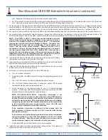
16. Install the cover plate using the provided eight sealing screws. Fully tighten all
eight screws by hand, then back off one full turn.
COVER PLATE
SEALING WASHERS
(UNDER EACH SCREW)
KEYBOARD
(OPTIONAL)
UNIVERSAL
MOUNT
MONITOR
RIGHT HAND
LOCKING TABS
LEFT HAND
LOCKING TABS
REAR COVER


