


5
100 Mbit/s connection (backbone port)
Two ports (ports 6 and 7) allow a 100 Mbit/s
backbone to be constructed.
– RS2-FX/FX: two ports complying with
100BASE-FX (SC sockets, multimode)
– RS2-FX/FX ST: two ports complying with
100BASE-FX (ST sockets, multimode)
– RS2-FX-SM/FX-SM: two ports complying
with 100BASE-FX (SC sockets, single-
mode)
– RS2-FX-SM/FX-LH: two ports complying
with 100BASE-FX (SC sockets, single-
mode: one port 1300 nm and one port
1550 nm)
– RS2-FX-LH/FX-LH: two ports complying
with 100BASE-FX (SC sockets, single-
mode: 1550 nm)
– RS2-TX/TX: two ports complying with
10/100BASE-T(X) (RJ45 sockets)
Factory settings: The backbone ports are
pre-configured to 100 MBit/s full duplex.
This configuration is necessary to build
redundant structures.
The backbone ports support full duplex and
half duplex mode. The TX ports also sup-
port autonegotiation and the autopolarity
function. Factory settings: Port 6 and port 7
are pre-configured to 100 Mbit/s, full
duplex.
Standby-Port
An 8-pin RJ45 socket (standby) is used to
connect two RS2-…/…/RS1 in redundancy
mode via the control line. The socket casing
is electrically connected to the front panel
of the RS2-…/…. The S and
Stby_Out- pins are electrically separated
from the operating voltage and the chassis
(relay contact).
To determine the maximum cable length of
the control line you measure its resistance
in back and forth direction. The direct cur-
rent resistance may amount up to 10 Ohm
(refer to the RS2 manual).
– Pin configuration
of the RJ45 socket:
– S: Pin 3, Stby_Out-: Pin 6
– : Pin 1, Stby_In-: Pin 2
– remaining pins: not used.
Fig. 4: Pin configuration of the standby
interface
n.c.
Pin 8
n.c.
Pin 7
Stby_Out-
Pin 6
n.c.
Pin 5
n.c.
Pin 4
Pin 3
S
Pin 2
Stby_In-
Pin 1
– with the
RM
switch the RM functionality
(Redundancy Manager) can be switched
on or off. State of delivery: switch in posi-
tion 0 (Off), i.e. RM function not active.
Note:
You should activate only one of the
two functions standby and RM on each
device.
If both functions are active simultaneously
the device will reset.
Fig. 2: 2-pin DIP switch on RS2-…/…
1.10 INTERFACES
10/100 MBit/s connection
Five 10/100 Mbit Ports (ports 1 to port 5, 8-
pin R45 sockets) on RS2-…/… allow termi-
nal equipment or five independent network
segments complying with the standards
IEEE 802.3 100BASE-TX / 10BASE-T to be
connected. These ports support autonego-
tiation and the autopolarity function.
Factory settings: autonegotiation active for
port 1 to port 5.
The socket casings are electrically connec-
ted to the front panel of the RS2-…/….The
pin configuration complies with MDI-X.
Always use port 1 to couple two network
segments (ref. chapter 2.3 “Redundant Cou-
pling of Network segments”).
– Pin configuration
of the RJ45 socket:
– TD+: pin 3, TD-: pin 6
– RD+: pin 1, RD-: pin 2
– remaining pins: not used.
Fig. 3: Pin configuration of an TP/TX
interface
n.c.
Pin 8
n.c.
Pin 7
TD-
Pin 6
n.c.
Pin 5
n.c.
Pin 4
Pin 3
TD+
Pin 2
RD-
Pin 1
RD+
1
0
Stand by
RM
Redundancy Mode
Redundancy Manager
V.24 interface (external management)
A serial interface for local connection of
– an external management station (VT100
terminal or a PC with corresponding ter-
minal emulation) is available via the RJ11
socket (V.24 interface). A link can thus be
established with the User Interface UI.
– an AutoConfiguration Adapter ACA 11 is
available via the RJ11 socket (V.24 interfa-
ce).
VT100 terminal settings:
– Speed:
9,600 Baud
– Data:
8 bit
– Stopbit:
1 bit
– Handshake: off
– Parity:
none
The V.24 interface baud rate can be configu-
red to 9,600 or 19,200 baud. The factory
default is 9,600 baud.
The socket casing is galvanically connected
to the front panel of the device. The signal
lines are galvanically separated from the
operating voltage (60 V isolation voltage)
and the front panel.
Note:
In chapter 6 „Technical data“ you
find the order number for the terminal
access cable which is to be ordered
separately.
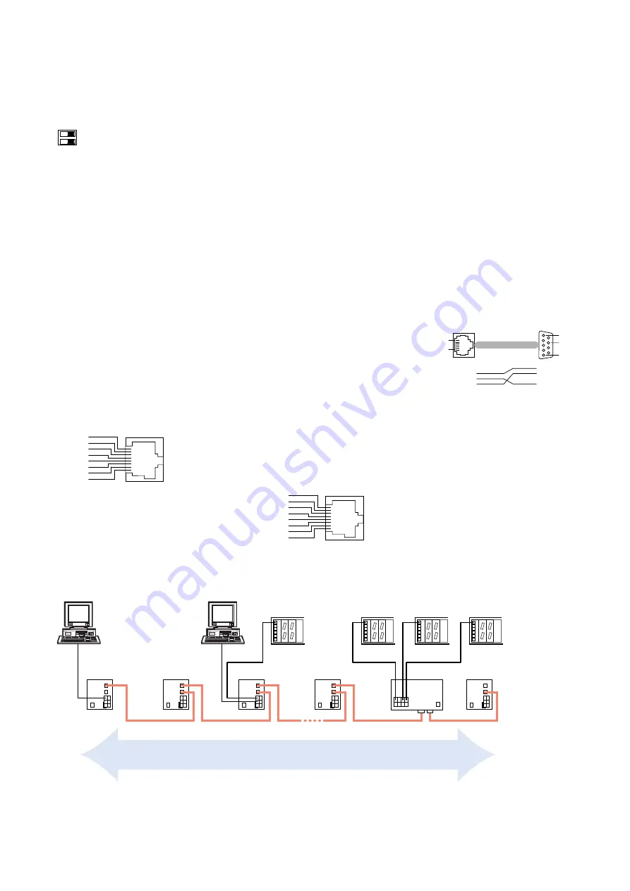
Fig. 5: Pin configuration of the V.24
interface
– AutoConfiguration Adapter ACA:
The ACA is a device for saving the confi-
guration data of a MICE, RS2 or MACH
3000 switch. If one switch should fail, the
ACA facilitates a conceivable simple
assumption of the configuration data by
an alternative switch of the same type.
In case of a reset the switch compares the
contents of the ACA with its own configu-
ration data. If the configuration data do
not correspond, the switch takes over the
configuration data of the ACA.
Pin 1
Pin 1
Pin 8
Pin 5
Pin 6
RJ11
DB9
2
3
5
1
2
3
4
5
6
CTS
n.c.
TX
GND
RX
RTS
RS2
RS2
RS2
RS2
RS1
Line structure
RS2
RS2:
RS2-TX/TX
RS2-FX/FX
RS2-FX/FX ST
RS2-FX-SM/FX-SM
RS2-FX-SM/FX-LH
RS2-FX-LH/FX-LH
Fig. 6: Line structure


