


5 Installation
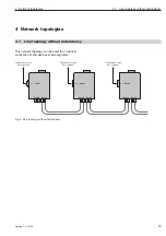
5.1 Installation guidelines
18
Version 1.0 03/06
Shield connections
Always observe the following points when installing bus
line shielding:
D
Secure the shield braid using metal cable clamps.
D
The clamps must fully enclose the shield and make
good contact (see Fig. 8).
D
Only contact the lines via the copper braid shield.
D
The shields of all cables which are routed into a
cabinet from the outside must be clamped at the
point of entry inside the cabinet and connected to the
cabinet ground with a large contact surface area.
D
When removing the cable jackets, it is important to
ensure that the braid shield of the cables is not
damaged. Tin-plated or galvanically stabilized surf-
aces are ideal for optimum contacting between
grounding elements. With zinc-plated surfaces, suit-
able threaded connections must be provided for the
required contacts. Painted surfaces at the contact
points are unsuitable.
D
Shield clamps/contact points should not be used as
strain relief devices. Contact with the shield bus could
otherwise deteriorate or break completely.
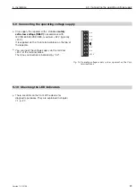
The power supply wires (+24 VDC and 0 V) for the
OZD 485 G12 BAS must not be laid in the same cable
duct as cables for load circuits.
The wires (+24 VDC and 0 V) should be twisted
together.
䊳
Standard recommendations for the arrangement of
devices and cables
EN 50174-2 contains recommendations for arranging
devices and cables which are aimed at reducing
mutual interference to a minimum.
D
Using bus line shields
It is important to observe the following when shielding
bus lines:
- Only use fully shielded lines. The shields of these
lines must be of sufficient thickness to satisfy the
legal requirements for interference radiated and
interference received.
䡲
- Always attach the shields at both ends of the bus
lines. The legal requirements regarding interference
radiated and interference received for your system
will only be satisfied if shields are connected at
both ends (CE symbol).
- Dismantle the shield of the bus cable completely
and put it on an equipotential rail. This rail must in
turn be connected with the function ground of the
OZD 485 G12 BAS by means of a short cable.
Note:
If differences in potential occur between the grounding
points, an inadmissably high compensating current could
flow across the shielding connected at both ends. Never
eliminate this problem by removing the shielding from the
bus line!
The following solution is permissible:
Lay an additional equipotential bonding cable parallel to
the bus line.
Fig. 8: Securing shielded lines using cable clamps and tube
clips (schematic diagram)
Содержание 943 893-321
Страница 6: ...4 Version 1 0 03 06...
Страница 8: ...6 Version 1 0 03 06...
Страница 12: ...2 Half duplex operation 10 Version 1 0 03 06...
Страница 14: ...3 Tristate recognition through permanent highHigh 12 Version 1 0 03 06...
Страница 18: ...4 Network topologies Subkapitel 16 Version 1 0 03 06...
Страница 26: ...5 Installation 24 Version 1 0 03 06...
Страница 32: ...7 Help with problems 30 Version 1 0 03 06...
Страница 35: ......


