


3
D
GB
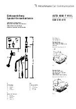
Einbauanleitung
Der Einbau der Versenkantenne
AUTA 4000 F 419 L erfolgt bei den angegebenen
Mercedes-Benz-Modellen in den linken hinteren
Kotflügel.
Im Kofferraum die linksseitige Auskleidung
entfernen. Für Kabelverlegung hintere Sitz-
bank und -kissen ausbauen.
Die Einbaustelle nach
Fig. 1
oder
2
anzeichnen
und ein Loch Ø 22 mm maßhaltig bohren
(
Fig. 3
). Zum Schutz des Lackes vorher mit
Klebeband abkleben. Die Bohrung entgraten,
zum Schutz gegen Korrosion die blanke
Kante mit Grundlack bestreichen und
antrocknen lassen.
In der Zwischenzeit das Antennenkabel
zusammen mit dem bereits verlegten Lei-
tungssatz durch die Mehrfachtülle unter die
Rücksitzbank, von dort unter der linken Ein-
stiegsleiste (bei Baureihe 201 im Kabelkanal)
bis vor den Fahrersitz nach vorne und von
dort zum Empfänger verlegen und einstecken.
Das Antennenkabel ist geräteseitig mit einem
abwinkelbaren Stecker versehen. Dadurch
kann der Stecker je nach Bedarf gerade oder
als Winkelstecker verwendet werden. Das
Abbiegen über den Führungsrücken bitte nur
von Hand durchführen, damit Kabel und
Stecker nicht verletzt werden (
Fig. 6
).
Die Dichttülle in die Karosseriebohrung ein-
setzen (
Fig. 3 und 4
).
Das Antennenkabel an der Antenne fest-
schrauben, den Kugelstutzen mit etwas
Antennenfett bestreichen (AUTA 115) und die
Antenne von unten in die Dichttülle ein-
drücken.
Die Antenne mit Halter am Schutzrohr gegen
das vorhandene Langloch am Karosseriesteg
anschrauben (
Fig. 6
).
Teleskop ausziehen, Neigung kontrollieren
(evt. Dichttülle etwas drehen); danach
Schrauben am Halter fest anziehen.
Das Masseband an vorhandenem Loch an
der Verstrebung festschrauben, Anlagefläche
vorher blank schaben und einfetten (
Fig. 6
).
Auskleidung im Kofferraum und Rücksitz wieder
einbauen.
Das Teleskop ist mit einem Stülpknopf aus-
gerüstet und kann von Hand gegriffen und
ausgezogen werden. Mit abgenommenem
Stülpknopf kann das Teleskop vollständig
versenkt und nur mit dem Schlüssel ausge-
zogen werden (
Fig. 5
).
Achten Sie bitte darauf, daß nach dem Einbau
der Antenne der Empfänger nachgetrimmt wird.
Am Antenneneingang des Gerätes ist ein von
außen bedienbarer Trimmer eingebaut.
Bei ganz ausgezogener Antenne einen schwach
einfallenden Sender im Mittelwellenbereich
(ca.1100 kHz bzw. nach Angaben des Geräte-
herstellers) einstellen und mit dem Anten-
nentrimmer größte Lautstärke einstellen.
Das unterste Rohr der Antenne muß stets voll-
ständig ausgezogen werden. Nur so ist ein ein-
wandfreier Empfang gewährleistet.
Reinigen Sie Ihre Antenne von Zeit zu Zeit von
anhaftendem Straßenstaub. Verwenden Sie nur
ganz wenig von unserem Spezialfett in Tuben
AUTA 235, oder benutzen Sie unser Autoanten-
nen-Pflegetüchlein AUTA 135, das gleichzeitig
reinigt und fettet.
Installation instructions
Installation of the retractable antenna
AUTA 4000 F 419 L left-side in the rear wing of
the stated Mercedes-Benz cars.
Remove left-side lining in the luggage-boot.
For cable laying detach the back seat.
Mark the installation point acc. to
fig. 1
or
2
,
and drill a 22 mm dia. hole (
fig. 3
). Before
drilling cover the paintwork with adhesive
tape for protecting. Remove the burr, spread
the bare edge with primer to protect against
corrosion and allow to dry.
In the meantime pass the antenna cable
together with the already installed cable set
through the multiple grommet under the back
seat, then along the left edge (in case of
series 201 in the cable channel) to the front
of the driver's seat, from there to the receiver
and plug-in.
At the radio end the antenna cable is fitted
with a plug that can be angled. So it can be
used straight or, if necessary, as an angled
plug. Please bend the plug only by hand to
avoid any damage of cable or plug (
fig. 6
).
Insert the sleeve into the drilled hole (
fig. 3
and 4
).
Tighten the antenna cable to the antenna
case, spread the spherical antenna head with
some special grease (AUTA 115) and push
the antenna from below through the sleeve
inserted before.
Fix the antenna with bracket at the protective
tube to the existing oblong hole in the car
body (
fig. 6
).
Extend the telescope, check the angle (turn
the sleeve, if necessary), then tighten the
screws at the bracket.
Fix the earthing tape to the existing hole at
the brace. Previously bare the connecting
surface and spread with grease (
fig. 6
).
Replace lining in the luggage-boot and back
seat.
On top the telescope is provided with a plastic
knob, which allows extending the antenna by
hand. If this knob is detached, the telescope
can be fully retracted and then only be exten-
ded by use of a special key (
fig. 5
).
Please make sure that the radio will be tuned
again after the antenna has been installed. On
the antenna input of the receiver there is an
incorporated trimmer that can be operated from
outside.
With antenna fully extended select a weak
station in the medium wave band (approx.
1100 kHz or acc. to the instructions of the manu-
facturer of the radio) and set the maximum volu-
me by means of the trimmer.
The lowest tube must be always fully extended
in order to ensure a good reception.
From time to time, clean the telescope of adhe-
ring road dust. Use only a little of our special
aerial grease AUTA 235, supplied in tubes, or
our car aerial tissue AUTA 135 for both, clea-
ning and greasing.
Instructions de montage
L'installation de l'antenne escamotable
AUTA 4000 F 419 L, se fait dans les modèles
indiqués de Mercedes-Benz sur l'aile arrière
gauche.
Enlever le revêtement du côté gauche du
coffre. Démonter la banquette arrière et le
coussin pour la pose des câbles.
Marquer l'emplacement du montage selon la
fig.1
ou
2
, percer un trou de 22 mm de Ø
ayant les dimensions prescrites (
fig. 3
). Coller
un ruban adhésif avant pour protéger la
laque. Supprimer les bavures du perçage,
enduire le bord nu de laque de fond pour
protéger contre la corrosion et laisser sécher.
Entre-temps, poser le câble d'antenne avec
le jeu de câbles déjà mis par le passe-câble
multiple sous la banquette arrière, delà vers
l'avant sous le rebord d'accès gauche (en
cas de série 201 dans le canal de câble) jus-
que devant le siège du conducteur et à partir
de là, au récepteur et enficher.
Le câble d'antenne est pourvu sur le côté de
l'appareil d'une connection à fiche pliable.
De ce fait, la fiche peut être utilisée si besoin
est, droite ou comme fiche coudée. Ne la
tordre que manuellement par dessus le tube
conducteur, afin que câble et fiche ne soient
pas endommagés (
fig. 6
).
Placer la manchette dans le perçage de la car-
rosserie (
fig. 3 et 4
).
Visser à fond le câble d'antenne à l'antenne,
enduire d'un peu de graisse le joint à bille
(AUTA 115) et appuyer l'antenne du dessous
dans la manchette déjà placée.
Visser l'antenne avec le support au tube contre
le trou longitudinal existant à la traverse de
carrosserie (
fig. 6
).
Sortir le télescope, contrôler l'inclinaison (tour-
ner un peu éventuellement la manchette);
ensuite serrer à fond les vis au support.
Visser à fond la bande de mise à la masse
au perçage existant à l'entroise, gratter à nu
avant la surface et graisser (
fig. 6
).
Remettre le revêtement du coffre et la ban-
quette arrière.
Le télescope est équipé d'un bouton à
retournement et peut être manipulé et sorti
manuellement. Le télescope peut être com-
plètement noyé avec le bouton à retournement
enlevé et être seulement sorti avec la clé (
fig. 5
).
Veuillez faire attention à ce que le récepteur soit
réadapté, après la pose de l'antenne. A l'entrée
de l'antenne de l'appareil, il est monté un con-
densateur de compensation réglable de l'ex-
térieur.
Lorsque l'antenne est entièrement sorti, choisir
un émetteur reçu faiblement dans les ondes
moyennes (env. 1100 kHz resp. selon données
du constructeur) et régler à puissance maximum.
Le tube le plus bas de l'antenne doit toujours
être sorti complètement. Seulement de cette
façon, il est possible d'avoit une réception par-
faite.
Débarrasser votre antenne des poussières
adhérentes de la rue, de temps en temps.
Utiliser très peu notre graisse spéciale sous
forme de tube AUTA 235, ou bien utiliser notre
essuie-antenne-auto AUTA 135 qui nettoie et
graisse en même temps.
F


