5.2 Basic Specifications
43
Because the SM7860 is designed to be embedded in an automated system in applications in which it charges
capacitors, it cannot be used with a continuous load. Figures 1 and 2 define the minimum cycle times at which
this automated system can operate based on the output voltage and capacitor capacitance.
For example, when charging a 25 V, 30
μ
F capacitor, a charge interval of approximately 37 ms can be read
from the point at which a line extending from the 30
μ
F position on the vertical axis intersects the 25 V line.
This figure (37 ms) defines the minimum cycle for the automated system.
The time (
T
) representing the interval during the 37 ms for which the SM7860 charges the capacitor at the full
power of 50 mA or 10 mA can be calculated as follows:
T
=
C
×
V
/
I
C
: Capacitor capacitance
V
: Voltage
I
: Current (50 mA)
Using values of 25 V, 30
μ
F, and 50 mA yields:
T
= 30
μ
F × 25 V / 50 mA
= 15 ms
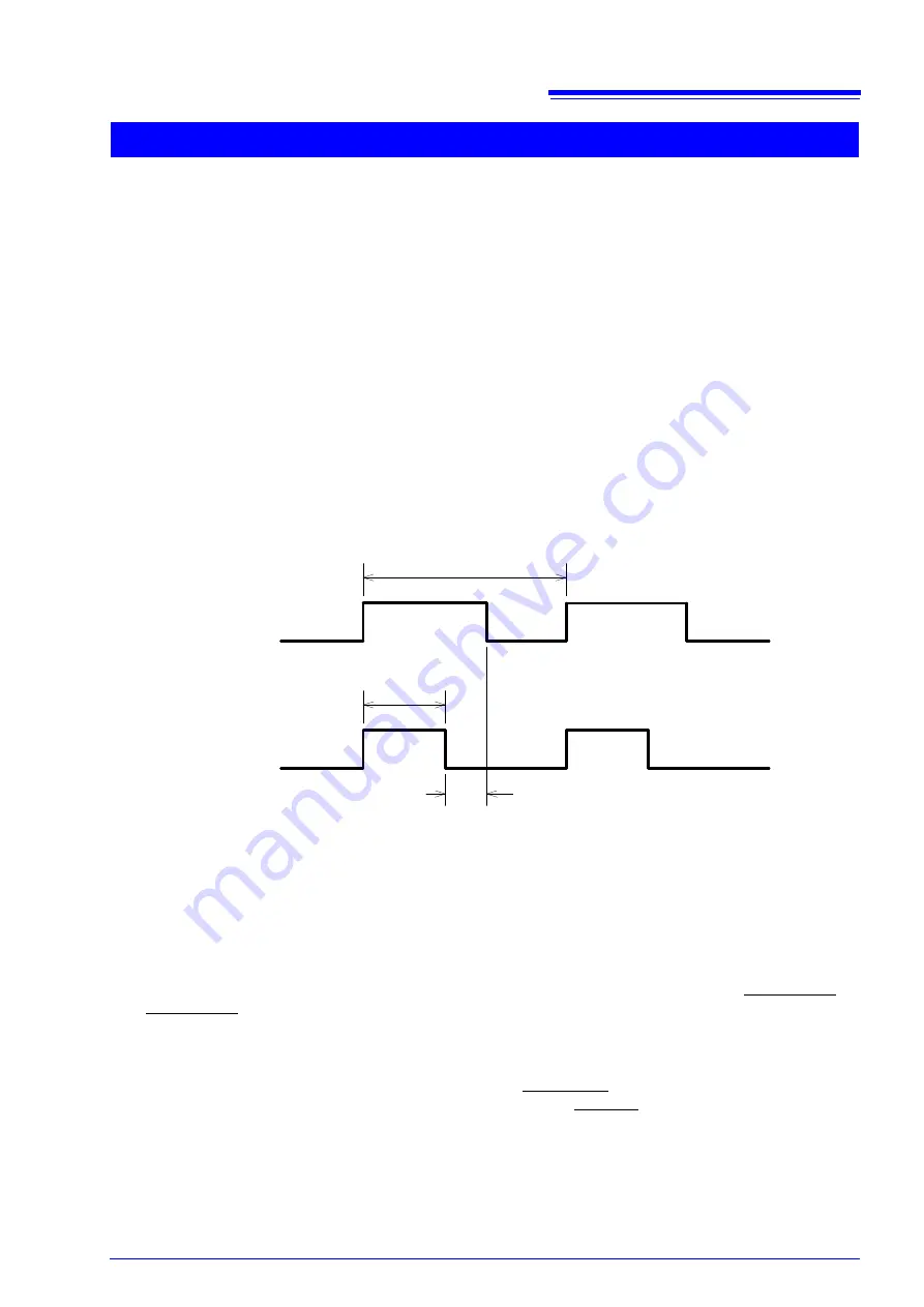
The following diagram expresses this as a timing chart:
During the 37 ms interval, the charging current flows for 15 ms, and almost no current flows for the remaining
22 ms. If, for example, the automated system's cycle time were 100 ms instead of 37 ms, the charging current
would flow for 15 ms, and almost no current would flow for the remaining 85 ms. This operation describes the
normal manner in which the SM7860 is used.
Using the instrument when there are shorted components
If the capacitor being charged were shorted, for example due to defective insulation, the charging current
would flow for the entire contact interval, rather than just 15 ms. If the test run is expected to include shorted
components, check each component before initiating testing and avoid applying current if shorted.
(1)
Design the system so that each of the external input (EXT I/O) signals, from OUT1(1)_ON to
OUT4(8)_ON, can be controlled (turned on and off) independently.
(2)
When outputting voltage from the SM7860, check each capacitor for a short before initiating testing.
(Have the automated system store the results of checks performed before testing, for example using
capacitance measurement.)
(3)
When a shorted component is encountered, turn the OUT(X)_ON signal for the shorted component's
channel off before turning the external input (EXT I/O) signal's OUTPUT signal on.
Using the instrument when capacitors are not mounted by the automated system
When capacitors are not properly mounted from the automated system's part feeder, the architecture of the
system may cause the SM7860's output to enter the shorted state. This issue can be addressed in the same
manner as described in "Using the instrument when there are shorted components" above.
Graph description and operating precautions
37 ms
15 ms
Contact
Movement
Contact
Movement
Automated system
operation
Charging current
Almost no current during this interval
Содержание SM7860-01
Страница 2: ......
Страница 10: ...Operating Precautions 6...
Страница 53: ......
Страница 54: ......


