


Operation and Screen Types
2
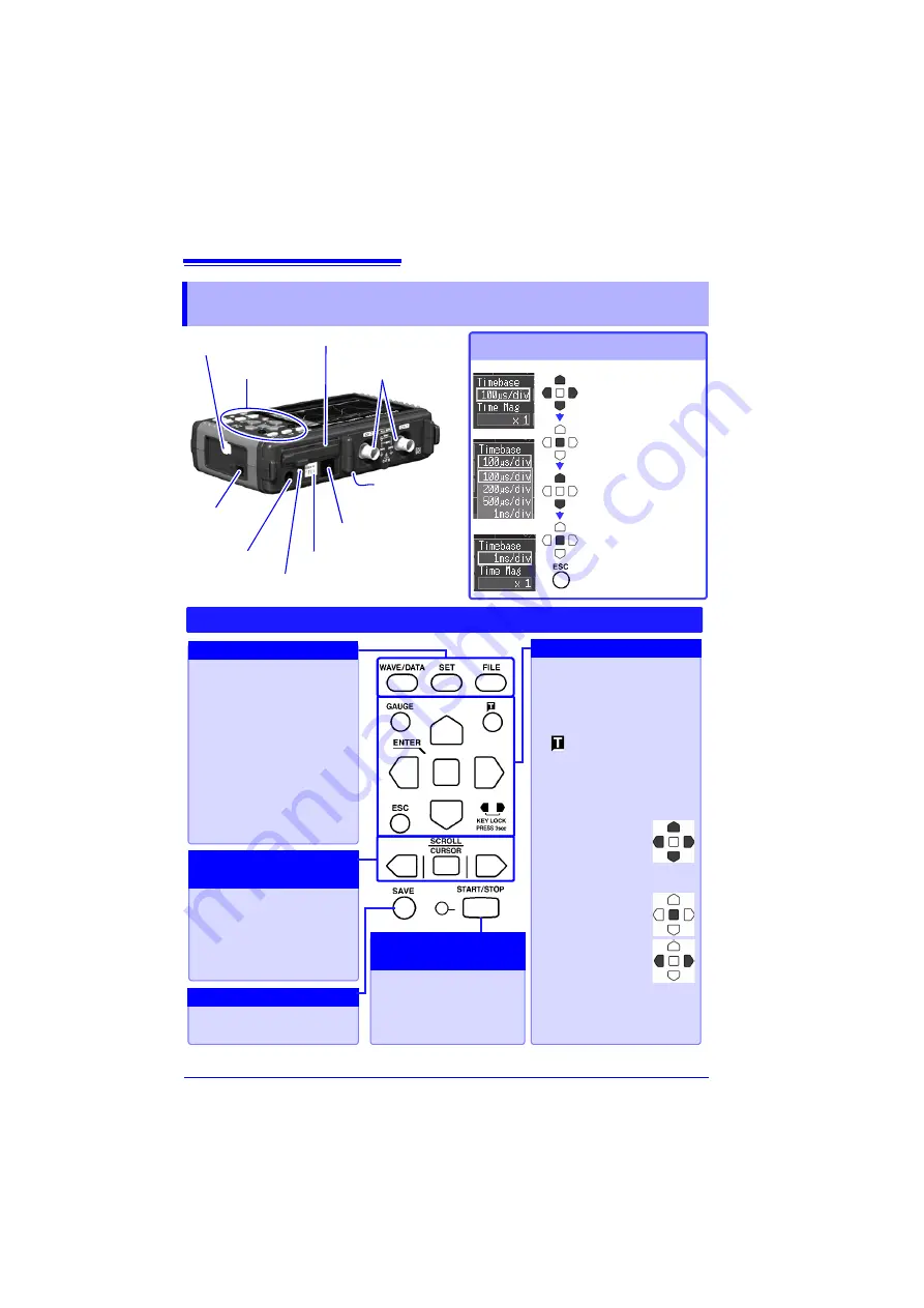
Operation and Screen Types
Select the item to
change.
Show available
setting options.
Select the desired
setting.
Changing screen contents
CF Card Slot
Logic Connector
External control terminals
AC Adapter
Socket
CHARGE LED
USB Port
POWER
Switch
Operating Keys
(Rear)
Battery
Compartment
Apply the new set-
ting,
or cancel it.
BNC Terminals
WAVE/DATA
Selects among waveform
screen displays (p. 3).
SET
Displays the Settings
screens, and switches
among the screen tabs with
each press (p. 3).
FILE
Displays file information
GAUGE
Alternately displays and
hides the measurement
scale on the Waveform
screen.
(Manual trigger)
Press to trigger manually.
ESC
Cancels changes to set-
tings.
Cursor Keys
Moves the position
of the cursor (blink-
ing selection) on
the screen.
ENTER
Accepts displayed
settings.
KEY LOCK
Disables keypad
operations. Press
and hold the left
and right cursor keys simul-
taneously for three seconds
to lock and unlock the keys.
Press to save data manual-
ly (p. 7).
Press the center key to se-
lect waveform scrolling or
A/B cursor movement, then
press the left and right cur-
sor keys to scroll or move
(p. 12).
Setup and display
Saving operations
Scroll waveforms and
read cursor values
Choose a screen
Start and stop measure-
ment. The LED at the left
lights green while mea-
suring.
Start and stop
measurement
Operating Keys
Содержание 8870-20
Страница 1: ...MEMORY HiCORDER Measurement Guide 8870 20 October 2013 Revised edition 4 8870B980 04 13 10H ...
Страница 2: ......
Страница 18: ...Analysis 16 ...
Страница 19: ......
Страница 20: ......


