


Maintenance 13
PLOW ASSEMBLY
PLOW ASSEMBLY
1. Place moldboard face down on cardboard
or other padding that will prevent scratches
in the paint.
Remove two side markers and four ship-
ping straps from the ends of the moldboard.
Save the bolts and nuts for reinstalling
markers later.
Remove the two 5/8” bolts through the cen-
ter ribs on the back of the moldboard, and
save for reinstallation later.
Remove the three hinge pins from the back
of the moldboard by driving out one spring
pin, and save for reinstallation.
Additional compression springs are includ-
ed with 8 1/2’ moldboards. Remove springs
and set aside for reassembly.
2. Open the frame crate and set aside the
power unit box, headlamp boxes and parts
box for later assembly.
Carefully lift the frame assembly by wrap-
ping straps or padded chains around both
ends of the 2 1/2” square tube at the rear of
the frame. Attach the frame assembly to the
moldboard by lining up the three bushings
on the frame with the three sets of bushings
on the moldboard.
Apply commercially available anti-seize lu-
bricant (not supplied) to the hinge pins to
prevent future corrosion, and reinstall the
hinge pins through the bushings. Secure
the hinge pins with spring pins.
Remove 3/4” lock nuts from the back of
each compression spring. Align each pull-
rod bushing with the upper set of holes in
the moldboard ribs and reinstall 5/8” bolts
and lock nuts. Tighten lock nuts only until
snug against ribs.
Assemble 3/4” lock nuts back onto pullrods
and tighten until compression springs mea-
sure 13” long. Do not overtighten springs.
GENERAL INFORMATION
WARNING: To prevent personal injury
or death, be certain to keep clear of
any parts that may drop when remov-
ing bundling straps, wires or brackets. Sup-
port heavy sections with hoist or blocks be-
fore removing wires or straps.
In the following instructions, left and right ma-
chine references are defined as being viewed
from the cab of the truck. Be certain that hy-
draulic hoses and electrical wires are safely
routed and allow full motion of moving parts.
Secure loose wires with plastic tie straps. Some
components are fastened at incorrect locations
for shipping purposes.
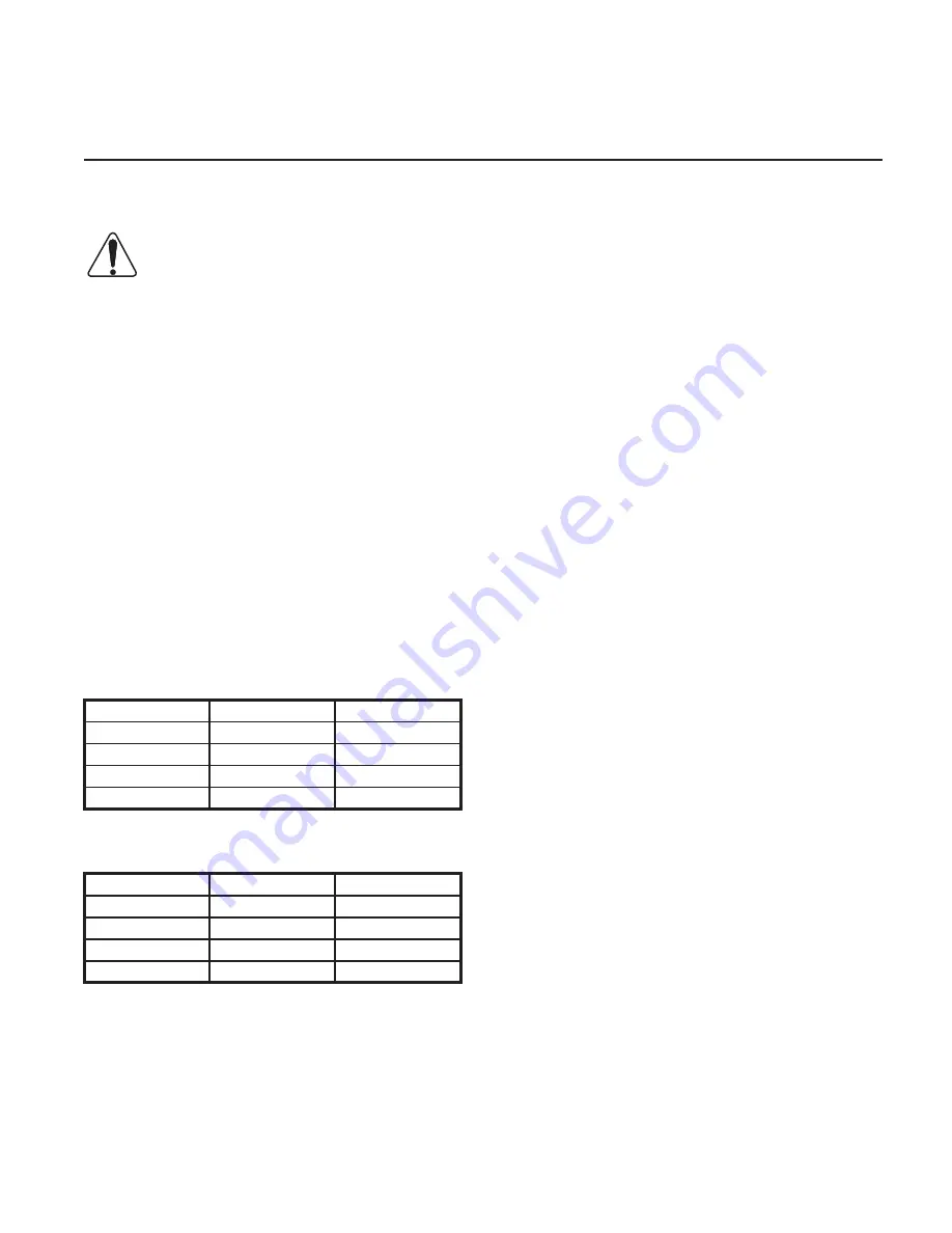
All hardware should be tightened only enough
to ensure safety during assembly. Torque hard-
ware to specified values, as shown in the follow-
ing chart, only after assembly has been com-
pleted.
GRADE 5 TYPE B & F LOCK NUT
TORQUE VALUES
Diameter
Ft-lbs.
N-m
5/16”
13-18
17-25
3/8”
23-33
31-44
1/2”
58-82
79-112
5/8”
117-165
158-223
GRADE 5 BOLT TORQUE VALUES*
Size
Ft-lbs.
N-m
1/4”
8-12
11-16
3/8”
29-41
39-56
1/2”
73-103
99-140
5/8”
146-206
198-279
* applications without lock nuts
Replace worn bolts and lock nuts with
grade 5 bolts and equivalent type B and type F
lock nuts. Type B lock nuts are plain hex; type F
lock nuts are flanged hex.
Содержание 2752
Страница 2: ......
Страница 26: ...24 Wiring Harness ...
Страница 27: ...Wiring Harness 25 DWG NO 5657 ...
Страница 28: ...26 Straight Plow Power Unit DWG NO 6586 ...
Страница 29: ...Power Unit Hydraulic Circuit Diagram 27 DWG NO 6600 ...