


X-AI 32 51
3 Product Description
HI 801 181 E Rev. 4.00
Page 15 of 58
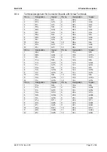
3.4.4
System Bus Indicators
The system bus LEDs are labeled
Sys
Bus.
LED
Color
Status
Description
On
Physical and logical connection to the system bus
module in slot 1.
Green
Blinking1
No physical connection to the system bus module in
slot 1.
A
Yellow Blinking1 The physical connection to the system bus module
in slot 1 has been established.
No connection to a (redundant) processor module
running in system operation.
On
Physical and logical connection to the system bus
module in slot 2.
Green
Blinking1
No physical connection to the system bus module in
slot 2.
B
Yellow Blinking1 The physical connection to the system bus module
in slot 2 has been established.
No connection to a (redundant) processor module
running in system operation.
A+B Off Off
Neither physical nor logical connection to the
system bus modules in slot 1 and slot 2.
Table 5:
System Bus Indicators
3.4.5 I/O
Indicators
LED
Color
Status
Description
On
The input current is > 4 mA or greater than the HIGH
switching point (dig) configured in SILworX.
Blinking2 Channel fault (module field or hardware fault). Input
current > 20 mA
Channel
1...32
Yellow
Off
The input current is < 4 mA or less than the LOW
switching point (dig) configured in SILworX.
Blinking2 Field fault on at least one channel or supply (open-circuit,
short-circuit, over-current, etc.)
Depending on the configured current thresholds.
Field
Red
Off
No field fault displayed!
Table 6:
I/O Indicators
Содержание X-AI 32 51
Страница 1: ...X AI 32 51 HIMax Analog Input Module Manual ...
Страница 57: ......


