8
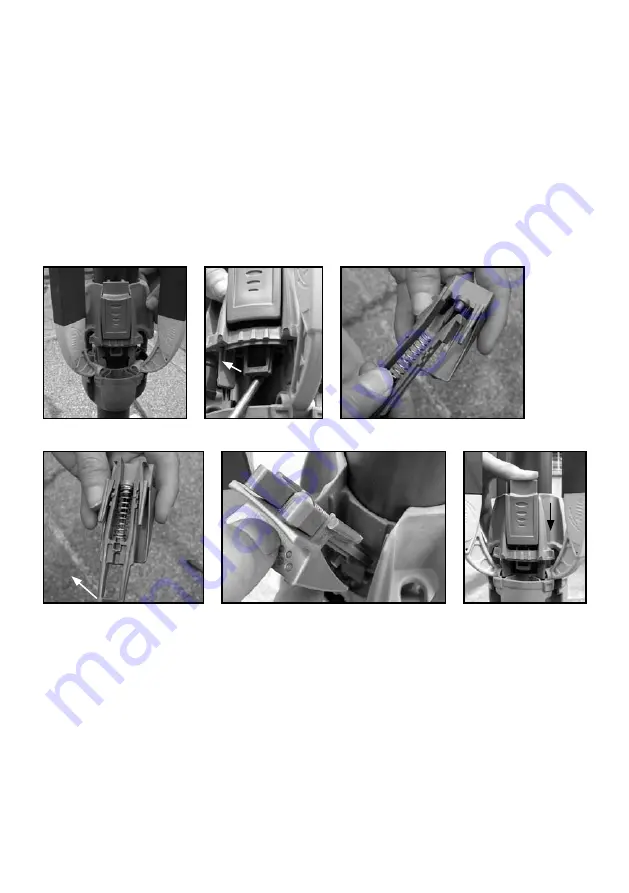
Item 5: Repairing the Latch Assembly
1. Disassemble the Lower Cross Assembly as described in Item 4, Steps 1 to 8 (Fig. 18).
2. Lever the Latch assembly off the retaining ledge (Fig. 19).
3. Service the Latch Assembly (Fig. 20).
4. Ensure when Locking Fork is replaced with the Sliding Latch, the lower snap detail
is facing towards the Main Standard (Fig. 21).
5. Slide the assembly into the locating slot until it has re-engaged the snap
detail (Fig. 22 and 23).
6. Re-assemble the Lower Cross Assembly (Fig. 23). Refer to Item 4, Steps 16, 17 and 18.
Fig. 18
Fig. 19
Fig. 20
Fig. 21
Fig. 22
Fig. 23
Содержание Rotary 400
Страница 1: ...Rotary Folding Hoists Installer s Manual To suit models Rotary 400TM Rotary 450TM Rotary 500TM ...
Страница 2: ......
Страница 7: ...7 Fig 11 Fig 12 Fig 13 Fig 14 Fig 15 Fig 16 Fig 17 ...
Страница 15: ...15 Notes Issue November 2007 ...
Страница 16: ......


