Hill-Rom P444A Скачать руководство пользователя страница 20

Warning and Caution Labels

Chapter 1: Introduction

TRANS

l

LIFT

TM

 Resident Stand Assist Service Manual (man173)

Page 1 - 13

1

Warning and Caution Labels

Figure 1-4.  Warning and Caution Labels

m173_063

Содержание P444A

Страница 1: ...SERVICE MANUAL TRANS LIFTTM Resident Stand Assist From Hill Rom Product No P444A For Parts Or Technical Assistance man173 USA 800 445 3720 Canada 800 267 2337 International Contact your distributor...

Страница 2: ...TRANSlLIFTTM Resident Stand Assist Service Manual man173 Page i TRANS LIFT Resident Stand Assist Service Manual Revisions man173 Revision Letter Pages Affected Date Original Issue August 1998...

Страница 3: ...SA Hill Rom is a registered trademark of Hill Rom Inc TRANS LIFTTM is a trademark of Hill Rom Inc The information contained in this manual is subject to change without notice Hill Rom makes no commitm...

Страница 4: ...nd Adjustment Procedures 1 3 Chapter 5 Parts List 1 4 Chapter 6 General Procedures 1 4 Chapter 7 Accessories 1 4 Typographical Conventions 1 4 Introduction 1 5 Overview 1 5 System Features 1 7 Specifi...

Страница 5: ...ion 2 18 Battery Charger Malfunction 2 19 Chapter 3 Theory of Operation Theory of Operation 3 3 Braking 3 3 Actuator 3 3 Handset 3 3 Battery 3 3 Battery Charger 3 4 Control Unit 3 4 Chapter 4 Removal...

Страница 6: ...Removal 4 14 Replacement 4 15 Battery Pack 4 16 Removal 4 16 Replacement 4 16 Control Box 4 17 Removal 4 17 Replacement 4 17 Mounting Post 4 18 Removal 4 18 Replacement 4 18 Knee Pad Assembly 4 19 Rem...

Страница 7: ...nges 5 7 Out of Warranty Exchanges 5 7 Recommended Spare Parts 5 8 TRANS LIFTTM Resident Stand Assist P444A 5 10 Base Assembly 5 12 Chapter 6 General Procedures Cleaning and Care 6 3 General Cleaning...

Страница 8: ...ion 1 3 Chapter 4 Removal Replacement and Adjustment Procedures 1 3 Chapter 5 Parts List 1 4 Chapter 6 General Procedures 1 4 Chapter 7 Accessories 1 4 Typographical Conventions 1 4 Introduction 1 5 O...

Страница 9: ...Chapter 1 Introduction Page 1 2 TRANSlLIFTTM Resident Stand Assist Service Manual man173 1 NOTES...

Страница 10: ...to equipment Organization This manual contains seven chapters Chapter 1 Introduction In addition to a brief description of this service manual chapter 1 also provides a product overview Chapter 2 Trou...

Страница 11: ...icons designed to improve readability and increase understanding of its content Note the following examples Standard text used for regular information Boldface text emphasizes a word or phrase NOTE se...

Страница 12: ...Introduction Chapter 1 Introduction TRANSlLIFTTM Resident Stand Assist Service Manual man173 Page 1 5 1 Introduction Overview Figure 1 3 TRANS LIFTTM Resident Stand Assist m173_062...

Страница 13: ...The TRANS LIFTTM Resident Stand Assist is highly mobile and independent of an AC electrical source because it uses a rechargeable battery pack The handset cord allows the caregiver the freedom to move...

Страница 14: ...ers Adjustable base frame for easier chair access Integral actuator clutch Emergency stop button Emergency down release Magnetic backed handset Handset cord offers 360 caregiver access Audible low bat...

Страница 15: ...h 24 61 cm Length 52 132 cm Weight 117 lb 53 12 kg Caster size 3 8 cm Floor to Base Clearance 4 625 11 75 cm Maximum angle of inclination up 70 Maximum angle of inclination down 14 Minimum wall cleara...

Страница 16: ...assists Battery Charger 110 120V AC 60 Hz Charging voltage 27 6V DC 2 Charging current 650 milliampere Regulations Standards and Codes TRANS LIFTTM Resident Stand Assist meets specifications UL 2601 1...

Страница 17: ...sist Preventive maintenance performed by unauthorized personnel could result in personal injury or equipment damage WARNING Adhere to the Infection Control Policies and Procedures outlined in the Safe...

Страница 18: ...n operating the spreader bar Ensure the wheelchair is removed from the support legs before decreasing the width Failure to do so could result in personal injury or equipment damage WARNING Ensure both...

Страница 19: ...ge 1 12 TRANSlLIFTTM Resident Stand Assist Service Manual man173 1 CAUTION Do not use bleach or chlorine to wash the sling Equipment damage could occur CAUTION Do not use harsh cleaners solvents or de...

Страница 20: ...Warning and Caution Labels Chapter 1 Introduction TRANSlLIFTTM Resident Stand Assist Service Manual man173 Page 1 13 1 Warning and Caution Labels Figure 1 4 Warning and Caution Labels m173_063...

Страница 21: ...Warning and Caution Labels Chapter 1 Introduction Page 1 14 TRANSlLIFTTM Resident Stand Assist Service Manual man173 1 NOTES...

Страница 22: ...oting Procedures Chapter Contents Getting Started 2 3 Initial Actions 2 3 Function Checks 2 4 Final Actions 2 9 Leg Spreader Malfunction 2 10 Control Box Malfunction 2 13 Battery Malfunction 2 15 Actu...

Страница 23: ...Chapter 2 Troubleshooting Procedures Page 2 2 TRANSlLIFTTM Resident Stand Assist Service Manual man173 2 NOTES...

Страница 24: ...e given order Start with Initial Actions to begin gathering information about the problem Perform the Function Checks to isolate or identify a problem and to verify the repair after completing each co...

Страница 25: ...The unit rolls smoothly and no casters limp bind or wobble Yes No Replace any caster that does not roll smoothly Refer to Front Caster on page 4 3 or Rear Caster on page 4 5 as appropriate 3 Engage t...

Страница 26: ...procedure 4 13 then return to these function checks 11 Inspect the column and push bar The column and push bar are in good condition and show no sign of cracks or distortion Yes No Replace the column...

Страница 27: ...endant refer to procedure 4 16 then continue with these function checks WARNING Do not stand directly under the lift arm while it is in motion Personal injury could result 19 Press the up button on th...

Страница 28: ...release on the top of the actuator NOTE The lift arm will not descend unless there is significant weight applied The lift arm slowly drifts down to its lowest position Yes No Replace the actuator refe...

Страница 29: ...tinue with these function checks If not replace the actuator refer to procedure 4 12 If this solves the problem continue with these function checks If not call Hill Rom Technical Support at 800 445 37...

Страница 30: ...ice Manual man173 Page 2 9 2 33 The TRANS LIFTTM Resident Stand Assist is operating normally Go to Final Actions on page 2 9 Final Actions 1 Complete the required preventive maintenance procedures See...

Страница 31: ...der Malfunction 1 Set the caster brakes 2 Remove the two hex head bolts A and two flatwashers B securing the base cover C to the back support subassembly D see figure 2 1 on page 2 10 Figure 2 1 Base...

Страница 32: ...4 6 If this solves the problem go to Final Actions on page 2 9 If not continue with step 5 5 Inspect the tie rod assemblies B The tie rod assemblies are firmly connected to the spreader shaft subassem...

Страница 33: ...ng Procedures Page 2 12 TRANSlLIFTTM Resident Stand Assist Service Manual man173 2 7 Perform the tie rod adjustment refer to procedure 4 4 This solves the problem Yes No Call Hill Rom Technical Suppor...

Страница 34: ...handset pendant plug and insert it firmly into the bottom of the control box If this solves the problem go to Final Actions on page 2 9 If not continue with step 4 4 The actuator cable is firmly plug...

Страница 35: ...Box Malfunction Chapter 2 Troubleshooting Procedures Page 2 14 TRANSlLIFTTM Resident Stand Assist Service Manual man173 2 8 The problem is not a control box malfunction Return to the Function Checks...

Страница 36: ...roblem go to Final Actions on page 2 9 If not call Hill Rom Technical Support at 800 445 3720 5 Turn the emergency stop button clockwise to release it if necessary and push either the up or down butto...

Страница 37: ...rol box and press either button The lift arm raises or lowers as appropriate Yes No Replace the actuator refer to procedure 4 12 then go to Final Actions on page 2 9 4 Perform the following a Press an...

Страница 38: ...o press in on the emergency down release under the emergency stop button on the control box The lift arm drifts slowly down to its lowest position Yes No Replace the actuator refer to procedure 4 12 I...

Страница 39: ...age 2 9 If not continue with step 3 3 Place your hand on the actuator and press the up button on the handset pendant You can feel slight vibrations from the actuator and the lift arm raises Yes No Go...

Страница 40: ...rger C see figure 2 3 on page 2 19 Figure 2 3 Battery Charger Power Cord Connection Yes No Plug the power cord A into the receptacle B on the side of the battery charger C Ensure that the locking tabs...

Страница 41: ...voltmeter for DC and check the reading at the battery charger terminals J and K The voltage measures 27 6V DC 2 and the current measures 650 mA Yes No Replace the battery charger refer to procedure 4...

Страница 42: ...Resident Stand Assist Service Manual man173 Page 3 1 3 Chapter 3 Theory of Operation Chapter Contents Theory of Operation 3 3 Braking 3 3 Actuator 3 3 Handset 3 3 Battery 3 3 Battery Charger 3 4 Cont...

Страница 43: ...Chapter 3 Theory of Operation Page 3 2 TRANSlLIFTTM Resident Stand Assist Service Manual man173 3 NOTES...

Страница 44: ...the lift arm A clutch in the motor prevents movement of the lift arm if it encounters any resistance when lowering the resident The actuator also contains an emergency down release button In the event...

Страница 45: ...the handset pendant and routes power and commands to the actuator The handset pendant is attached to the control unit by a multi pin cable connector The control unit is attached to the actuator throug...

Страница 46: ...Theory of Operation Chapter 3 Theory of Operation TRANSlLIFTTM Resident Stand Assist Service Manual man173 Page 3 5 3 Figure 3 1 TRANS LIFTTM Resident Stand Assist m173_062...

Страница 47: ...Theory of Operation Chapter 3 Theory of Operation Page 3 6 TRANSlLIFTTM Resident Stand Assist Service Manual man173 3 NOTES...

Страница 48: ...Caster 4 3 Removal 4 3 Replacement 4 4 Rear Caster 4 5 Removal 4 5 Replacement 4 6 Base Cover 4 7 Removal 4 7 Replacement 4 7 Tie Rod Assembly 4 8 Removal 4 8 Replacement 4 9 Adjustment 4 9 Leg Subass...

Страница 49: ...placement 4 17 Mounting Post 4 18 Removal 4 18 Replacement 4 18 Knee Pad Assembly 4 19 Removal 4 19 Replacement 4 19 Actuator 4 20 Removal 4 20 Replacement 4 21 Lift Arm 4 22 Removal 4 22 Replacement...

Страница 50: ...er protective cloth on the floor before turning the unit on its back Failure to do so could result in equipment finish damage 1 Lay a sheet or other protective cloth on the floor Place the unit on its...

Страница 51: ...rocedures Page 4 4 TRANSlLIFTTM Resident Stand Assist Service Manual man173 4 Replacement WARNING Use a new elastic stop nut Installation of used elastic stop nuts could result in personal injury or e...

Страница 52: ...loor before turning the unit on its side Failure to do so could result in equipment finish damage 1 Lay a sheet or other protective cloth on the floor Place the unit on the side opposite from the cast...

Страница 53: ...rocedures Page 4 6 TRANSlLIFTTM Resident Stand Assist Service Manual man173 4 Replacement WARNING Use a new elastic stop nut Installation of used elastic stop nuts could result in personal injury or e...

Страница 54: ...ls required Socket head wrench Removal 1 Set the caster brakes 2 Remove the two hex head bolts A and two flatwashers B securing the base cover C to the back support subassembly D see figure 4 3 on pag...

Страница 55: ...ning the unit on its back Failure to do so could result in equipment finish damage 1 Lay a sheet or other protective cloth on the floor Place the unit on its back 2 Remove the base cover refer to proc...

Страница 56: ...bar function 3 If necessary perform the adjustment procedure below 4 Install the base cover Adjustment 1 Remove the hex nut A securing the tie rod assembly B to the spreader shaft subassembly C see f...

Страница 57: ...o do so could result in equipment finish damage 1 Lay a sheet or other protective cloth on the floor Place the unit on its back 2 Remove the base cover refer to procedure 4 3 3 Remove the tie rod asse...

Страница 58: ...Assist Service Manual man173 Page 4 11 4 6 Remove the front caster F from the leg subassembly A refer to procedure 4 1 Replacement WARNING Use a new elastic stop nut Installation of used elastic stop...

Страница 59: ...Removal 1 Set the caster brakes 2 Remove the base cover refer to procedure 4 3 3 Remove the tie rod assemblies refer to procedure 4 4 4 Remove the roll pin A securing the pedal assembly B to the spre...

Страница 60: ...Shaft and Pedal Subassemblies Chapter 4 Removal Replacement and Adjustment Procedures TRANSlLIFTTM Resident Stand Assist Service Manual man173 Page 4 13 4 Replacement Perform the removal procedure in...

Страница 61: ...service on the unit Failure to do so could result in personal injury 1 Set the brakes on both rear casters WARNING Push in the emergency stop button on the control box to lock out power and prevent i...

Страница 62: ...4 15 4 Figure 4 8 Base Assembly Removal WARNING The column is heavy Have a partner assist in lifting the column Failure to do so could result in personal injury 4 Lift the column C from the base assem...

Страница 63: ...Tools required None Removal 1 Pull the battery lock clamp A until it disengages the top of the mounting post B see figure 4 9 on page 4 16 Figure 4 9 Battery Pack Removal 2 Remove the battery pack C f...

Страница 64: ...battery pack refer to procedure 4 8 2 Disconnect the handset A and control box wiring harness B from the control box C see figure 4 10 on page 4 17 Figure 4 10 Control Box Removal 3 Remove the contro...

Страница 65: ...nting Post Tools required Screwdriver Removal 1 Remove the battery pack refer to procedure 4 8 2 Remove the control box refer to procedure 4 9 3 Remove the screws A and mounting post B from the column...

Страница 66: ...ssist Service Manual man173 Page 4 19 4 4 11 Knee Pad Assembly Tools required Screwdriver Removal Remove the hex head bolts A and knee pad assembly B from the knee support C see figure 4 12 on page 4...

Страница 67: ...the brakes on both rear casters 2 If possible lower the lift arm to its lowest position WARNING Push in the emergency stop button on the control box to lock out power and prevent inadvertant movement...

Страница 68: ...l 6 Remove the actuator C from the lift arm D and column stand assembly E Replacement 1 Place the emergency down label F onto the actuator C WARNING Use a new elastic stop nut Installation of used ela...

Страница 69: ...trol box wiring harness 2 Remove the actuator refer to procedure 4 12 3 Remove the shoulder bolt A and elastic stop nut B from the lift arm assembly C see figure 4 14 on page 4 22 Discard the elastic...

Страница 70: ...Stand Assist Service Manual man173 Page 4 23 4 WARNING Use a new elastic stop nut Installation of used elastic stop nuts could result in personal injury or equipment damage 2 Perform the removal proc...

Страница 71: ...iring harness 2 Remove all attachments to the column stand assembly 3 Remove the two hex head bolts A and two flatwashers B from the column stand assembly C see figure 4 15 on page 4 24 Figure 4 15 Co...

Страница 72: ...ilure to do so could result in personal injury or equipment damage 1 Unplug the power cord from its power supply 2 Remove the screw A that holds the battery charger B to the wall mounting bracket C se...

Страница 73: ...charger mounting tab G with the mounting hole H on the wall mounting bracket C 2 Install a screw A to attach the battery charger B to the wall mounting bracket C 3 Align the locks on the battery charg...

Страница 74: ...rvice on the unit Failure to do so could result in personal injury 1 Set the brakes on both rear casters WARNING Push in the emergency stop button on the control box to lock out power and prevent inad...

Страница 75: ...handset pendant C from the top of the column Replacement 1 Place the magnetic back of the handset pendant C against the pendant storage label on the top of the column NOTE The handset pendant plug mus...

Страница 76: ...ve the battery charger from the wall mounting bracket refer to procedure 4 15 NOTE It is not necessary to completely remove the screws that secure the wall mounting bracket to the wall Back them out f...

Страница 77: ...7 Wall Mounting Bracket Chapter 4 Removal Replacement and Adjustment Procedures Page 4 30 TRANSlLIFTTM Resident Stand Assist Service Manual man173 4 Replacement Perform the removal steps in reverse or...

Страница 78: ...Page 5 1 5 Chapter 5 Parts List Chapter Contents Warranty 5 3 Service Parts Ordering 5 5 Exchange Policy 5 7 In Warranty Exchanges 5 7 Out of Warranty Exchanges 5 7 Recommended Spare Parts 5 8 TRANS L...

Страница 79: ...Chapter 5 Parts List Page 5 2 TRANSlLIFTTM Resident Stand Assist Service Manual man173 5 NOTES...

Страница 80: ...number product model number serial number and description of problem A qualified specialist will provide via telephone United States and Canada or FAX Outside the United States and Canada troubleshoo...

Страница 81: ...Warranty Chapter 5 Parts List Page 5 4 TRANSlLIFTTM Resident Stand Assist Service Manual man173 5 NOTES...

Страница 82: ...he product identification label A see figure 5 1 on page 5 5 Figure 5 1 Product Identification Label Location Call Hill Rom Technical Support at 800 445 3720 with the following information Six digit c...

Страница 83: ...S HILL ROM COMPANY 1069 STATE ROUTE 46 E BATESVILLE IN 47006 9167 Address all return goods to ATTN SERVICE STORES DISTRIBUTION CENTER DOOR D23 HILL ROM COMPANY COUNTY ROAD 300E BATESVILLE IN 47006 916...

Страница 84: ...ts will show the full selling price only for Hill Rom s internal use Do not confuse this price with your price Do not return any parts without an RMA number When parts products have been requested to...

Страница 85: ...nits or more Table 5 1 Recommended Spare Parts Part Number Quantity Description 100 008 0033 2 Stand assist sling assembly 030 019 0104 1 Hand set 030 014 0010 1 Battery pack 100 007 0038 1 Non slip t...

Страница 86: ...Recommended Spare Parts Chapter 5 Parts List TRANSlLIFTTM Resident Stand Assist Service Manual man173 Page 5 9 5 NOTES...

Страница 87: ...ident Stand Assist P444A Chapter 5 Parts List Page 5 10 TRANSlLIFTTM Resident Stand Assist Service Manual man173 5 TRANS LIFTTM Resident Stand Assist P444A Figure 5 2 TRANS LIFTTM Resident Stand Assis...

Страница 88: ...0 019 0103 1 Charger battery 11 001 033 0098 3 Screw self tapping 10 x 3 4 12 030 019 0102 1 Box control 13 030 014 0010 1 Battery pack 14 030 019 0104 1 Hand set 15 001 007 0008 2 Plug plastic cap 16...

Страница 89: ...Base Assembly Chapter 5 Parts List Page 5 12 TRANSlLIFTTM Resident Stand Assist Service Manual man173 5 Base Assembly Figure 5 3 Base Assembly m173_001...

Страница 90: ...070 0040 1 Back support subassembly 5 330 001 0023 2 Caster rear 6 001 003 0039 4 Bolt carriage 7 001 003 0047 2 Bolt shoulder 1 2 x 3 8 001 004 0090 4 Nut hex 9 433 010 0016 1 Spreader shaft subassem...

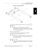
Страница 91: ...Base Assembly Chapter 5 Parts List Page 5 14 TRANSlLIFTTM Resident Stand Assist Service Manual man173 5 NOTES...

Страница 92: ...ning and Care 6 3 General Cleaning 6 3 Steam Cleaning 6 3 Hard to Clean Spots 6 3 Disinfection 6 4 Stand Assist Sling Cleaning 6 4 Battery Pack Disposal 6 4 Lubrication Requirements 6 5 Preventive Mai...

Страница 93: ...Chapter 6 General Procedures Page 6 2 TRANSlLIFTTM Resident Stand Assist Service Manual man173 6 NOTES...

Страница 94: ...r equipment damage could occur CAUTION Do not use bleach or chlorine to wash the sling Equipment damage could occur CAUTION Do not use harsh cleaners solvents or detergents Equipment damage could occu...

Страница 95: ...3 Wash the sling for at least 3 minutes at a minimum temperature of 160 F 71 C not to exceed maximum temperature of 176 F 80 C Dry in a conventional dryer at a maximum temperature of 176 F 80 C WARNI...

Страница 96: ...quipment damage could occur Oilite bearings and bushings are utilized in several places on the system By retaining oil the pores give a self lubricating quality to the bearings and bushings If any sil...

Страница 97: ...sting not only meet JCAHO requirements but will help to ensure a long operative life for the TRANS LIFTTM Resident Stand Assist PM will minimize downtime due to excessive wear The following PM schedul...

Страница 98: ...he lift arm to the full upper limit and pull the actuator emergency down release pin Ensure the lift arm slowly drifts to the lowest position Replace the actuator emergency down release pin and run th...

Страница 99: ...Inc Manufacturer Sling assembly Hand set Lift limits Emergency stop button Actuator down release Frame Lift arm bolts and elastic stop nuts Model Number Front casters Rear casters Rear caster braking...

Страница 100: ...tand Assist Service Manual man173 Page 6 9 6 Tool and Supply Requirements The following tools are required to service the TRANS LIFTTM Resident Stand Assist Screwdriver Phillips head screwdriver 3 8 o...

Страница 101: ...Tool and Supply Requirements Chapter 6 General Procedures Page 6 10 TRANSlLIFTTM Resident Stand Assist Service Manual man173 6 NOTES...

Страница 102: ...TRANSlLIFTTM Resident Stand Assist Service Manual man173 Page 7 1 7 Chapter 7 Accessories Chapter Contents The TRANS LIFTTM Resident Stand Assist has no accessories...

Страница 103: ...Chapter 7 Accessories Page 7 2 TRANSlLIFTTM Resident Stand Assist Service Manual man173 7 NOTES...

Отзывы: