


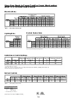


5
Set Shims On Basehorse Locations
Locate basehorse positions along chalk
lines. Spot shim packs at each
basehorse location.
4
Level Floor. Use Laser Transit
Leveling is necessary to assure proper
case alignment. Locate highest point on
chalk line as reference for
determining height of shim-pack
levelers. A laser transit is recommend-
ed for precision.
7
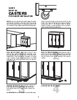
Position Next Case In Line Up
Roll case approximately 6’ from adjoin-
ing case. Remove casters on the end
nearest to the next case. Allow casters
to remain on opposite end to assist in
pushing cases together - then remove
them.
6
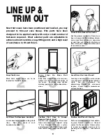
LINE UP &
TRIM OUT
BASE RAIL
BASE RAIL
1
Consult With General Contractor
Ask the general contractor if there have
been changes in the building dimen-
sions since the print you are using was
issued. Also, ask the points of reference
from which you should take dimensions
to locate the cases.
2
Snap Chalk Lines
Mark floor where cases are to be
located for the entire lineup.
3
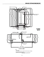
S n a p L i n e s O n B a s e R a i l
Locations
Snap lines where base rails are posi-
tioned, not the front or back edges of
the cases. See case cross section
drawing, page 3, for rail location dimen-
sions.
6
Position First Case In Lineup,
Remove Casters, Level
Roll first case into position. Raise case
from end under cross support using
“J” bar. Remove cotter pins, casters,
and outriggers. [CAUTION! Keep hands
from under case] Level case on shims.
Now that cases have been positioned and leveled, you may
proceed to trim-out case lineup. Trim parts have been
designed to be applied easily with only a small number of
fasteners required. Most external parts are adjustable to
achieve almost invisible, snug-fitting joints and a high level
of excellence in fit and finish.
Содержание KRZH
Страница 2: ......
Страница 4: ......
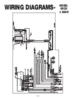
Страница 16: ...12 WIRING DIAGRAMS MODEL KRZH 2 DOOR ...
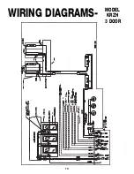
Страница 17: ...13 WIRING DIAGRAMS MODEL KRZH 3 DOOR ...
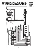
Страница 18: ...14 WIRING DIAGRAMS MODEL KRZH 4 DOOR ...
Страница 19: ...15 WIRING DIAGRAMS MODEL KRZH 5 DOOR ...
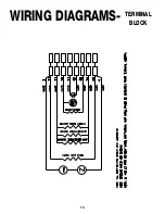
Страница 20: ...16 WIRING DIAGRAMS TERMINAL BLOCK ...
Страница 21: ...17 WIRING DIAGRAMS GFI ...
Страница 28: ...24 PARTS ORDERING MODEL KRZH 1 22 23 24 4 9 15 17 19 55 25 E09 E11 E10 E20 11 12 13 36 69 56 81 82 87 88 ...