


Network Video Recorder User Manual
77
Chapter 8 Disk Array
Purpose
Disk array is a data storage virtualization technology that combines multiple physical disk drive
components into a single logical unit. An array stores data over multiple HDDs to provide enough
redundancy so that data can be recovered if one disk fails. Data is distributed across the drives in
one of several ways called "RAID levels", depending on what level of redundancy and performance
is required.
8.1 Create Disk Array
Purpose
The device supports the disk array that is realized by software. You can enable the RAID function as
required. Two ways are available for creating array: one-touch configuration and manual
configuration. The following flow chart shows the process of creating array.
8.1.1 Enable RAID
Purpose
Perform the following steps to enable the disk array function.
Step 1
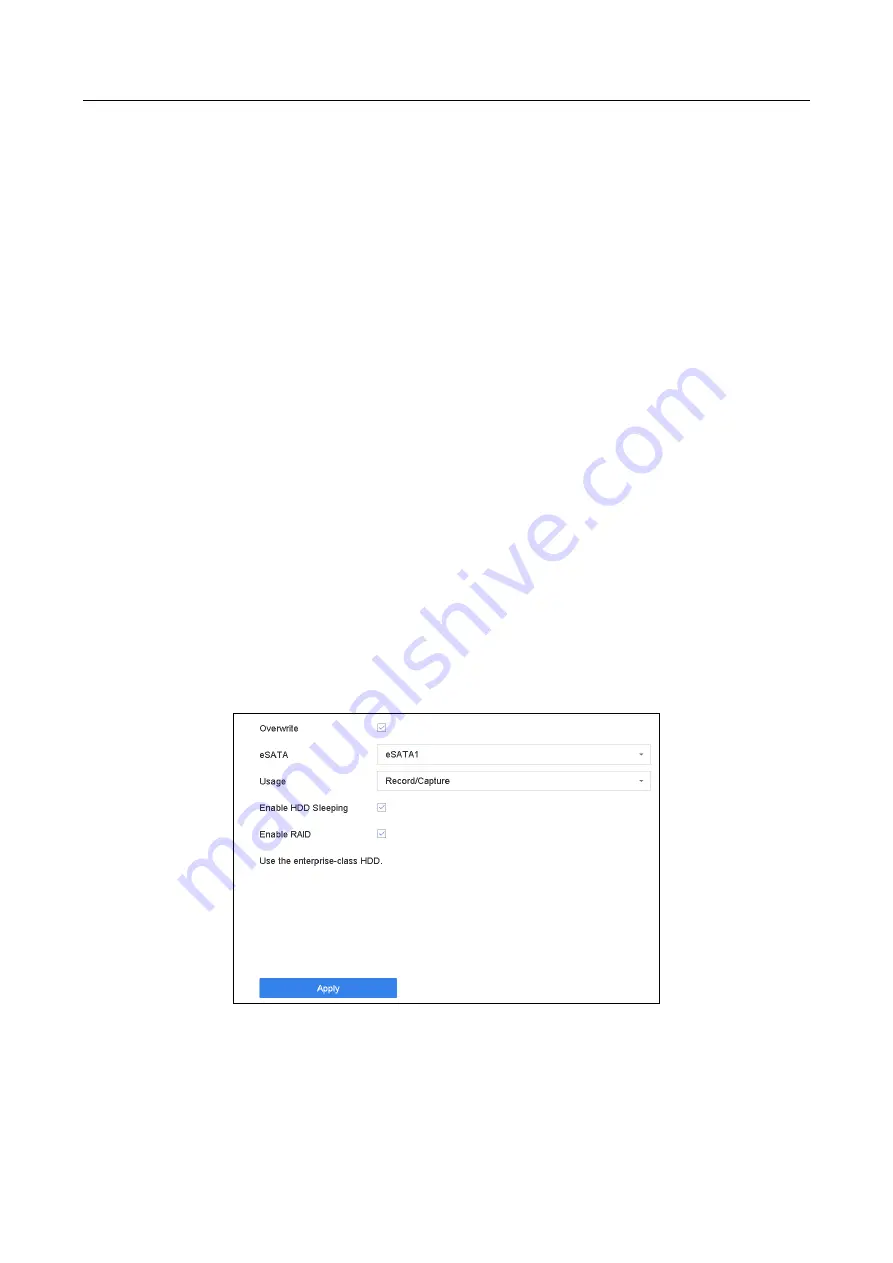
Go to Storage > Advanced.
Figure 8-1
Advanced
Step 2
Check Enable RAID.
Step 3
Click Apply.
Step 4
Reboot device to take effect the settings.
Содержание iDS-9616NXI-I16/16S
Страница 1: ...Network Video Recorder User Manual...
Страница 89: ...Network Video Recorder User Manual 88 Step 2 Click a created search conditon to quickly search files...
Страница 115: ...Network Video Recorder User Manual 114 Figure 11 12 Alarm Output...
Страница 155: ...Network Video Recorder User Manual 154 Figure 16 7 Port Settings...
Страница 198: ...Network Video Recorder User Manual 197 UD07876B...


