background image

Network Video Recorder User Manual   

175 


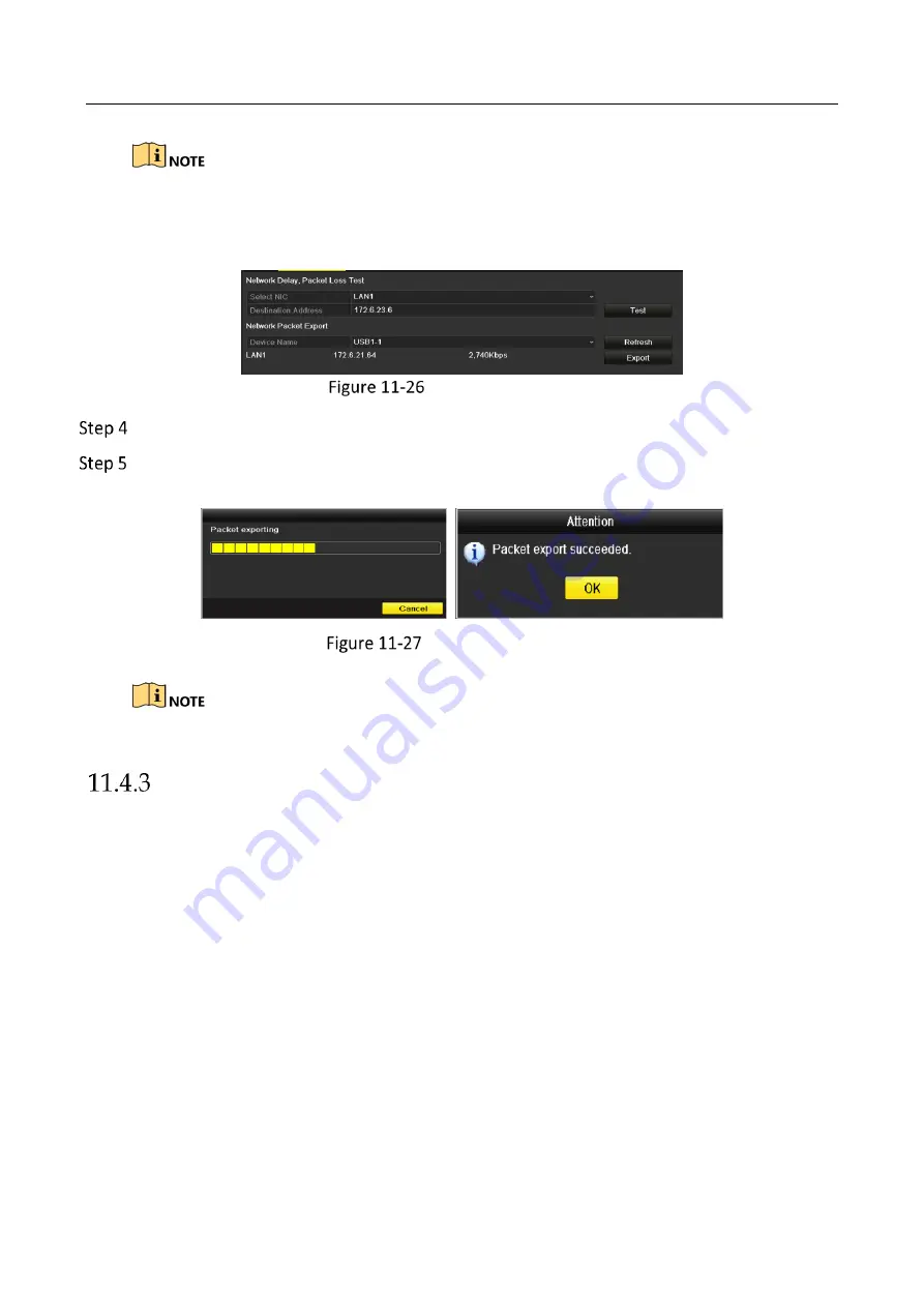
Click 

Refresh

 button if the connected local backup device cannot be displayed. When it fails to 

detect the backup device, please check whether it is compatible with the NVR. You can format the 
backup device if the format is incorrect. 


Export Network Packet 


Click 

Export

 button to start exporting. 


After the exporting is complete, click 

OK

 to finish the packet export, as shown in Figure 11-

27. 


Packet Export Attention 


Up to 1M data can be exported each time.


Checking the Network Status 

Purpose: 

You can also check the network status and quick set the network parameters in this interface. 

Steps: 

Click the 

Status

 button on the lower- right corner of the page. 

Содержание HWN-2104H-4P

Страница 1: ...Network Video Recorder User Manual UD04699B ...

Страница 2: ...entioned below are the properties of their respective owners Legal Disclaimer TO THE MAXIMUM EXTENT PERMITTED BY APPLICABLE LAW THE PRODUCT DESCRIBED WITH ITS HARDWARE SOFTWARE AND FIRMWARE IS PROVIDED AS IS WITH ALL FAULTS AND ERRORS AND HIKVISION MAKES NO WARRANTIES EXPRESS OR IMPLIED INCLUDING WITHOUT LIMITATION MERCHANTABILITY SATISFACTORY QUALITY FITNESS FOR A PARTICULAR PURPOSE AND NON INFRI...

Страница 3: ...ence 2 This device must accept any interference received including interference that may cause undesired operation EU Conformity Statement This product and if applicable the supplied accessories too are marked with CE and comply therefore with the applicable harmonized European standards listed under the EMC Directive 2014 30 EU the LVD Directive 2014 35 EU the RoHS Directive 2011 65 EU 2012 19 EU...

Страница 4: ...ovides additional information to emphasize or supplement important points of the main text Indicates a potentially hazardous situation which if not avoided could result in equipment damage data loss performance degradation or unexpected results Indicates a hazard with a high level of risk which if not avoided will result in death or serious injury ...

Страница 5: ...he device turn off the power at once and unplug the power cable and then please contact the service center Preventive and Cautionary Tips Before connecting and operating your device please be advised of the following tips Ensure unit is installed in a well ventilated dust free environment Unit is designed for indoor use only Keep all liquids away from the device Ensure environmental conditions mee...

Страница 6: ...esolution and VGA video output at up to 2K resolution Multiple screen display in live view is supported and the display sequence of channels is adjustable Live view screen can be switched in group Manual switch and auto switch are provided and the auto switch interval is configurable Configurable main stream and sub stream for the live view Quick setting menu is provided for live view Motion detec...

Страница 7: ...ime etc Smart search for the selected area in the video Zooming in when playback Reverse playback of multi channel Supports pause play reverse speed up speed down skip forward and skip backward when playback and locating by dragging the mouse Supports thumbnails view and fast view during playback Up to 16 ch synchronous playback at 1080p real time Supports playback by transcoded stream Supports en...

Страница 8: ... PoE network interfaces for the 16P models Long distance 100 300 m network transmission via PoE for P models IPv6 is supported TCP IP protocol DHCP DNS DDNS NTP SADP SMTP SNMP NFS and iSCSI are supported TCP UDP and RTP for unicast Auto Manual port mapping by UPnPTM Support access by Hik Connect Remote web browser access by HTTPS ensures high security The ANR Automatic Network Replenishment functi...

Страница 9: ...t stop alarm output Remote PTZ control Remote JPEG capture Virtual host function is provided to get access and manage the IP camera directly Two way audio and voice broadcasting Embedded WEB server Development Scalability SDK for Windows system Source code of application software for demo Development support and training for application system ...

Страница 10: ...0 and HWN 2100M Series 28 HWN 2100 P and HWN 2100M P Series 28 HWN 2100MH W Series 30 HWN 4100MH and HWN 4200MH Series 31 HWN 4100MH P and HWN 4200MH P Series 31 Chapter 2 Getting Started 33 Device Startup and Activation 33 Starting Up and Shutting Down the NVR 33 Activating Your Device 34 Using the Unlock Pattern for Login 36 Login and Logout 39 Resetting Your Password 40 Using Wizard for Basic C...

Страница 11: ...rols 71 Calling Patrols 72 Customizing Patterns 73 Calling Patterns 74 Customizing Linear Scan Limit 74 Calling Linear Scan 75 One touch Park 76 PTZ Control Panel 78 Chapter 5 Recording Settings 80 Configuring Parameters 80 Configuring Recording Schedule 84 Configuring Motion Detection Recording 88 Configuring Alarm Triggered Recording 90 Configuring VCA Event Recording 92 Manual Recording 94 Conf...

Страница 12: ...File Management 122 Chapter 7 Backup 123 Backing up Record Files 123 Quick Export 123 Backing up by Normal Video 125 Backing up by Event Search 128 Backing up Video Clips or Captured Playback Pictures 129 Managing Backup Devices 130 Chapter 8 Alarm Settings 131 Setting Motion Detection Alarm 131 Setting Sensor Alarms 133 Detecting Video Loss Alarm 136 Detecting Video Tampering Alarm 138 Handling E...

Страница 13: ... Configuring Hik Connect 162 Configuring DDNS 163 Configuring NTP Server 165 Configuring SNMP 165 Configuring More Settings 166 Configuring HTTPS Port 167 Configuring Email 169 Configuring NAT 171 Configuring Virtual Host 173 Checking Network Traffic 174 Configuring Network Detection 176 Testing Network Delay and Packet Loss 176 Exporting Network Packet 176 Checking the Network Status 177 Checking...

Страница 14: ...ng System Information 201 Searching Exporting Log Files 202 Importing Exporting IP Camera Info 204 Importing Exporting Configuration Files 205 Upgrading System 206 Upgrading by Local Backup Device 206 Upgrading by FTP 206 Restoring Default Settings 208 Chapter 15 Others 209 Configuring RS 232 Serial Port 209 Configuring General Settings 209 Configuring DST Settings 211 Configuring More Settings 21...

Страница 15: ...WN 2100H P and HWN 2100 P Series Description of Front Panel HWN 4100MH P Series HWN 4100MH P Series No Icon Description 1 Indicator turns red when NVR is powered up 2 Indicator lights in red when data is being read from or written to HDD 3 Indicator blinks blue when network connection is functioning properly ...

Страница 16: ...ard Disk Drive HDD HWN 2100 HWN 2100 M H W and HWN 4200MH P Series The front panel vaires according to different models HWN 2100 HWN 2100 M H W and HWN 4200MH P Series Panel Description IR Remote Control Operations The NVR may also be controlled with the included IR remote control shown in Figure 1 4 No Name Connections 1 POWER Turns green when NVR is powered up 2 HDD Flickers red when data is bei...

Страница 17: ... a specific NVR by changing the Device ID as follows Pairing Enabling the IR Remote to a Specific NVR optional You can pair an IR Remote to a specific Hikvision NVR by creating a user defined Device ID This feature is useful when using multiple IR Remotes and NVRs On the NVR Go to General More Settings Type a number 255 digits maximum into the Device No field On the IR Remote Press the DEV button ...

Страница 18: ...functions proceed as follows Press the DEV key on the IR Remote Any existing Device ID will be erased from the unit s memory and it will no longer function with the NVR Re enabling the IR Remote requires pairing to a NVR See Pairing the IR Remote to a Specific NVR optional above The keys on the remote control closely resemble the ones on the front panel See the table 1 4 ...

Страница 19: ...Network Video Recorder User Manual 18 IR Remote Functions ...

Страница 20: ...Network Video Recorder User Manual 19 No Name Function Description ...

Страница 21: ...r Is Not Logged On 1 Hold Power On Off button 1 down for five seconds to display the user name password prompt 2 Press the Enter button 12 to display the on screen keyboard 3 Input the user name 4 Press the Enter button 12 to accept input and dismiss the on screen keyboard 5 Use the Down Arrow button 12 to move to the Password field 6 Input password use on screen keyboard or numeric buttons 3 for ...

Страница 22: ...alphabet symbols and numerals 6 REC Enter Manual Record setting menu Call a PTZ preset by using the numeric buttons in PTZ control settings Turn audio on off in Playback mode 7 PLAY Go to Playback mode Auto scan in the PTZ Control menu 8 INFO Reserved 9 VOIP Switches between main and spot output Zooms out the image in PTZ control mode 10 MENU Return to Main menu after successful login N A Show hid...

Страница 23: ...have installed batteries properly in the remote control And you have to aim the remote control at the IR receiver in the front panel If there is no response after you press any button on the remote follow the procedure below to troubleshoot Go to Menu Settings General More Settings by operating the front control panel or the mouse Check and remember NVR ID The default ID is 255 This ID is valid fo...

Страница 24: ... and the polarities of the batteries are not reversed Batteries are fresh and not out of charge IR receiver is not obstructed No fluorescent lamp is used nearby If the remote still can t function properly please change a remote and try again or contact the device provider ...

Страница 25: ...vider The operation of the mouse Description of the Mouse Control Name Action Description Left Click Single Click Live view Select channel and show the quick set menu Menu Select and enter Double Click Live view Switch between single screen and multi screen Click and Drag PTZ control pan tilt and zoom Video tampering privacy mask and motion detection Select target area Digital zoom in Drag and sel...

Страница 26: ...Keyboard 1 Soft Keyboard 2 Description of the buttons on the soft keyboard Description of the Soft Keyboard Icons Icon Description Icon Description Number English letter Lowercase Uppercase Backspace Switch the keyboard Space Positioning the cursor Exit Symbols Reserved ...

Страница 27: ...12 VDC power supply 2 VGA Interface DB9 connector for VGA output Display local video output and menu 3 HDMI Interface HDMI video output connector 4 USB Interface Universal Serial Bus USB ports for additional devices such as USB mouse and USB Hard Disk Drive HDD 5 LAN Network Interface 1 10 100 1000 Mbps self adaptive Ethernet interface 6 Ground Ground needs to be connected when NVR starts up ...

Страница 28: ...ut and menu 3 HDMI Interface HDMI video output connector 4 USB Interface Universal Serial Bus USB ports for additional devices such as USB mouse and USB Hard Disk Drive HDD 5 LAN Network Interface 1 10 100 1000 Mbps self adaptive Ethernet interface 6 Ground Ground needs to be connected when NVR starts up 7 Network Interfaces with PoE function Network interfaces for the cameras and to provide power...

Страница 29: ...deo output connector 4 Network Interface Connector for LAN Local Area Network 5 Audio Out RCA connector for audio output 6 VGA Output DB9 connector for VGA output Display local video output and menu 7 USB Interface Universal Serial Bus USB ports for additional devices such as USB mouse and USB Hard Disk Drive HDD 8 Ground Ground needs to be connected when NVR starts up HWN 2100 P and HWN 2100M P S...

Страница 30: ... 4 Network Interface Connector for LAN Local Area Network 5 Audio Out RCA connector for audio output 6 VGA Output DB9 connector for VGA output Display local video output and menu 7 USB Interface Universal Serial Bus USB ports for additional devices such as USB mouse and USB Hard Disk Drive HDD 8 Ground Ground needs to be connected when NVR starts up 9 Network Interfaces with PoE function Network i...

Страница 31: ...n 1 Wi Fi Antenna Wi Fi antenna interface 2 Power supply 12 VDC power supply 3 Audio out 1 RCA connectors for audio output 4 VGA VGA video output connector 5 HDMI HDMI video output connector 6 LAN One RJ 45 10M 100M self adaptive Ethernet interfaces provided 7 Wi Fi Antenna Wi Fi antenna interface 8 USB Two USB 2 0 interface 9 Ground Ground needs to be connected when device starts up ...

Страница 32: ...or audio input 3 HDMI Interface HDMI video output connector 4 LAN Network Interface 1 10 100 1000 Mbps self adaptive Ethernet interface 5 Audio Out RCA connector for audio output 6 VGA Interface DB9 connector for VGA output Display local video output and menu 7 USB Interface Universal Serial Bus USB ports for additional devices such as USB mouse and USB Hard Disk Drive HDD 8 Ground Ground needs to...

Страница 33: ...aptive Ethernet interface 5 Audio Out RCA connector for audio output 6 VGA Interface DB9 connector for VGA output Display local video output and menu 7 USB Interface Universal Serial Bus USB ports for additional devices such as USB mouse and USB Hard Disk Drive HDD 8 Ground Ground needs to be connected when NVR starts up 9 Power Switch Switch for turning on off the device 10 Network Interfaces wit...

Страница 34: ...y UPS be used in conjunction with the device The Power indicator LED on the front panel should be red indicating the device gets the power supply Press the POWER button on the front panel The Power indicator LED should turn blue indicating that the unit begins to start up After startup the Power indicator LED remains blue A splash screen with the status of the HDD appears on the monitor The row of...

Страница 35: ...e NVR In the Shutdown menu you can also reboot the NVR Enter the Shutdown menu by clicking Menu Shutdown Click the Logout button to lock the NVR or the Reboot button to reboot the NVR Activating Your Device Purpose For the first time access you need to activate the device by setting an admin password No operation is allowed before activation You can also activate the device via Web Browser SADP or...

Страница 36: ...word monthly or weekly can better protect your product Click OK to save the password and activate the device When the device is activated the system pops up the message box to remind you to remember the password And you can click Yes to continue to export the GUID file for the future password resetting Export GUID File Remind Insert the U flash disk to your device and export the GUID file to the U...

Страница 37: ...t protocol Attention Interface Using the Unlock Pattern for Login For the Admin user you can configure the unlock pattern for device login Configuring the Unlock Pattern After the device is activated you can enter the following interface to configure the device unlock pattern Set Unlock Pattern Use the mouse to draw a pattern among the 9 dots on the screen Release the mouse when the pattern is don...

Страница 38: ... least 4 dots to draw the pattern Each dot can be connected for once only Draw the same pattern again to confirm it When the two patterns match the pattern is configured successfully Confirm the Pattern If the two patterns are different you must set the pattern again ...

Страница 39: ...mission to unlock the device Please configure the pattern first before unlocking Please refer to Configuring the Unlock Pattern Right click the mouse on the screen and select the menu to enter the interface as shown in Figure 2 8 Draw the Unlock Pattern Draw the pre defined pattern to unlock to enter the menu operation ...

Страница 40: ...attern for more than 5 times the system will switch to the normal login mode automatically Normal Login Dialog Box Login and Logout User Login Purpose If NVR has logged out you must login the device before operating the menu and other functions Select the User Name in the dropdown list Login Interface Input password Click OK to log in When you forget the password of the admin you can click Forget ...

Страница 41: ...er you have logged out the system menu operation on the screen is invalid It is required to input a user name and password to unlock the system Resetting Your Password When you forget the password of the admin you can reset the password by importing the GUID file The GUID file must be exported and saved in the local U flash disk after you have activated the device refer to Chapter 2 1 2 Activating...

Страница 42: ...e new admin password Refer to Chapter 2 1 2 Activating Your Device for details Click OK to set the new password You can export the new GUID file to the U flash disk for future password resetting When the new password is set the original GUID file will be invalid The new GUID file should be exported for future password resetting You can also enter the User User Management interface to edit the admi...

Страница 43: ...rd at that moment click the Cancel button You can also choose to use the Setup Wizard next time by leaving the Start wizard when the device starts checkbox checked Click Next button to enter the date and time settings window as shown in Figure 2 16 Date and Time Settings After the time settings click Next button which takes you back to the Network Setup Wizard window as shown in the following figu...

Страница 44: ...11 2 1 Configuring Hik Connect for detailed instructions Click Next button after you configured the basic network parameters Then you will enter the Advanced Network Parameter interface You can enable UPnP DDNS and set other ports according to your need Advanced Network Parameters Click Next button after you configured the network parameters which takes you to the HDD Management window shown in Fi...

Страница 45: ...e IP Camera and the Security status shows whether it is active or inactive Before adding the camera make sure the IP camera to be added is in active status If the camera is in inactive status you can click the inactive icon of the camera to set the password to activate it You can also select multiple cameras from the list and click the One touch Activate to activate the cameras in batch Click the ...

Страница 46: ...of Enable H 265 the NVR can automatically switch to the H 265 stream of IP camera which supports H 265 video format for the initial access Click Next button Configure the recording for the added IP Cameras Record Settings Click OK to complete the startup Setup Wizard ...

Страница 47: ... Camera Camera to enter the IP camera management interface For the IP camera detected online in the same network segment the Password status shows whether it is active or inactive IP Camera Management Interface Click the inactive icon of the camera to enter the following interface to activate it You can also select multiple cameras from the list and click the One touch Activate to activate the cam...

Страница 48: ...specially in the high security system resetting the password monthly or weekly can better protect your product Click OK to finish the acitavting of the IP camera And the security status of camera will be changed to Active Adding the Online IP Cameras Purpose The main function of the NVR is to connect the network cameras and record the video got from it So before you can get a live view or record o...

Страница 49: ... Or you can choose to custom add the IP camera by editing the parameters in the corresponding textfiled and then click the Add button to add it OPTION 2 Select the Add IP Camera option from the right click menu in live view mode or click Menu Camera Camera to enter the IP camera management interface Adding IP Camera Interface The online cameras with same network segment will be detected and displa...

Страница 50: ... list Make sure the camera to add has already been activated For the encoders with multiple channels only check the Channel Port checkbox in the pop up window as shown in the following figure and click OK to add multiple channels Selecting Multiple Channels OPTION 3 On the IP Camera Management interface click the Custom Adding button to pop up the Add IP Camera Custom interface Custom Adding IP Ca...

Страница 51: ...description of the icons Description of Icons Icon Explanation Icon Explanation Edit basic parameters of the camera Add the detected IP camera The camera is disconnected you can click the icon to get the exception information of camera Delete the IP camera Play the live video of the connected camera Advanced settings of the camera Upgrade the connected IP camera Security Show the security status o...

Страница 52: ...ed IP Cameras Enabling the H 265 Stream Access You can check the checkbox of Enable H 265 the NVR can automatically switch to the H 265 stream of IP camera which supports H 265 video format for the initial access Editing the Connected IP Cameras and Configuring Customized Protocols After the adding of the IP cameras the basic information of the camera lists in the page you can configure the basic ...

Страница 53: ...an choose the channel to connect by selecting the channel port No in the dropdown list Click OK to save the settings and exit the editing interface To edit advanced parameters Drag the horizontal scroll bar to the right side and click the icon Network Configuration of the Camera You can edit the network information and the password of the camera ...

Страница 54: ...d with the standard protocols you can configure the customized protocols for them Click the Protocol button in the custom adding IP camera interface to enter the protocol management interface Protocol Management Interface There are 16 customized protocols provided in the system you can edit the protocol name and choose whether to enable the sub stream Choose the protocol type of transmission and c...

Страница 55: ...eam or the sub stream is not needed leave the checkbox empty Type The network camera adopting custom protocol must support getting stream through standard RTSP Transfer Protocol Select the transfer protocol for the custom protocol Port Set the port No for the custom protocol Path Set the resource path for the custom protocol E g ch1 main av_stream The protocol type and the transfer protocols must ...

Страница 56: ...to the online network cameras And the PoE interface supports the Plug and Play function Before you start Connect the network cameras via the PoE interfaces Enter the Camera Management interface Menu Camera IP Camera List of Connected Cameras The cameras connecting to the PoE interface cannot be deleted in this menu Click the button and select the Adding Method in the drop down list Plug and Play I...

Страница 57: ...can disable the PoE interface by selecting the manual while the current channel can be used as a normal channel and the parameters can also be edited Input the IP address the user name and password of administrator manually and click OK to add the IP camera Edit IP Camera Interface Manual ...

Страница 58: ...Enter the PoE Configuration interface Menu Camera Camera PoE Configuration Click the radio button of each POE channel to switch and You can click the radio button of PoE Channel to enable or disable the long network cable mode ON Long distance 100 300 meters network transmissions via POE interface OFF Short distance 100 meters network transmission via POE interface Configure PoE Interface ...

Страница 59: ...nt IP camera models and cable materials When the transmission distance reaches 100 to 250 meters you must use the CAT5E or CAT6 network cable to connect with the PoE interface When the transmission distance reaches 250 to 300 meters you must use the CAT6 network cable to connect with the PoE interface Refer to the Appendix 错误 未找到引用源 错误 未找到引用源 for the list of IP cameras You can check the connecting...

Страница 60: ...the upper right of the screen for each channel showing the status of the record and alarm in the channel so that you can know whether the channel is recorded or whether there are alarms occur as soon as possible Description of Live View Icons Icons Description Alarm video loss video tampering motion detection VCA and sensor alarm Record manual record schedule record motion detection VCA and alarm ...

Страница 61: ...nuous record and motion detection record are supported Output Mode select the output mode to Standard Bright Gentle or Vivid Add IP Camera the shortcut to the IP camera management interface Playback playback the recorded videos for current day Aux Monitor the NVR checks the connection of the output interfaces to define the main and auxiliary output interfaces The priority level for the main and au...

Страница 62: ...umeric button E g Press 2 to display only the screen for channel 2 Show multi screen Press the PREV FOCUS button Manually switch screens Next screen right down direction button Previous screen left up direction button Auto switch Press Enter button Playback Press Play button Switch between main and aux output Press Main Aux button Using the Mouse in Live View Mouse Operation in Live View ...

Страница 63: ... Enter the IP Camera Management interface and manage the cameras Playback Enter the playback interface and start playing back the video of the selected channel immediately PTZ Enter the PTZ control interface Output Mode Four modes of output supported including Standard Bright Gentle and Vivid Aux Monitor Switch to the auxiliary output mode and the operation for the main output is disabled The dwel...

Страница 64: ...be selected from a dropdown list Next Screen When displaying less than the maximum number of cameras in Live View clicking this feature will switch to the next set of displays Playback Enter into Playback mode PTZ Control Enter PTZ Control mode Main Monitor Enter Main operation mode In the live view mode of the main output monitor the menu operation is not available while Aux output mode is enable...

Страница 65: ...tant Playback only shows the record in last five minutes If no record is found it means there is no record during the last five minutes Digital Zoom is for zooming in the live image You can zoom in the image to different proportions 1 to16X by moving the sliding bar from to You can also scroll the mouse wheel to control the zoom in out Digital Zoom Image Settings icon can be selected to enter the ...

Страница 66: ... detection function can be used to detect the human faces in live view mode and save in HDD When there are human faces with the specified size detected in the front of the camera the device will capture the human face and save in HDD Move the mouse onto the icon to show the real time stream information including the frame rate bitrate resolution and stream type Information ...

Страница 67: ...this menu include Video Output Interface Selects the output to configure the settings Live View Mode Designates the display mode to be used for Live View Dwell Time The time in seconds to dwell between switching of channels when enabling auto switch in Live View Enable Audio Output Enables disables audio output for the selected video output Volume Adjust the volume of live view playback and two wa...

Страница 68: ... stop all the live view 4 Click the Apply button to save the setting You can also click and drag the camera to the desired window on the live view interface to set the camera order Set the stream type for live view of camera 1 Click the More Settings to enter the more settings interface 2 Select the camera to configure from the list 3 Select the stream type to main stream sub stream or Auto Stream...

Страница 69: ...fecting the image quality channel zero encoding is supported as an option for you Enter the Live View Settings interface Menu Configuration Live View Select the Channel Zero Encoding tab Live View Channel Zero Encoding Check the checkbox after Enable Channel Zero Encoding Configure the Frame Rate Max Bitrate Mode and Max Bitrate After you set the Channel Zero encoding you can get a view in the rem...

Страница 70: ...re to set the parameters for PTZ The configuring of the PTZ parameters should be done before you control the PTZ camera Enter the PTZ Settings interface Menu Camera PTZ PTZ Settings Click the PTZ Parameters button to set the PTZ parameters PTZ General Choose the camera for PTZ setting in the Camera dropdown list ...

Страница 71: ...Z protocols Customizing Presets Purpose Follow the steps to set the Preset location which you want the PTZ camera to point to when an event takes place Enter the PTZ Control interface Menu Camera PTZ PTZ Settings Use the directional button to wheel the camera to the location where you want to set preset and the zoom and focus operations can be recorded in the preset as well Enter the preset No 1 2...

Страница 72: ...ontrol icon in the quick setting bar or select the PTZ option in the right click menu to show the PTZ control panel Choose Camera in the dropdown list Click the button to show the general settings of the PTZ control PTZ Panel General Click to enter the preset No in the corresponding text field Click the Call Preset button to call it Customizing Patrols Purpose Patrols can be set to move the PTZ to...

Страница 73: ...atrol The Duration refers to the time span to stay at the corresponding key point The Speed defines the speed at which the PTZ will move from one key point to the next Click the Add button to add the next key point to the patrol or you can click the OK button to save the key point to the patrol You can delete all the key points by clicking the Clear button for the selected patrol or click the Clea...

Страница 74: ...ettings of the PTZ control PTZ Panel General Select a patrol in the dropdown list and click the Call Patrol button to call it You can click the Stop Patrol button to stop calling it Customizing Patterns Purpose Patterns can be set by recording the movement of the PTZ You can call the pattern to make the PTZ movement according to the predefined path Enter the PTZ Control interface Menu Camera PTZ P...

Страница 75: ...interface Or press the PTZ button on the front panel or click the PTZ Control icon in the quick setting bar or select the PTZ option in the right click menu to show the PTZ control panel Click the button to show the general settings of the PTZ control PTZ Panel General Click the Call Pattern button to call it Click the Stop Pattern button to stop calling it Customizing Linear Scan Limit Purpose Th...

Страница 76: ...ell the angle from the left limit to the right limit should be no more than 180º Calling Linear Scan Before operating this function make sure the connected camera supports the linear scan and is in HIKVISION protocol Purpose Follow the procedure to call the linear scan in the predefined scan range Click the button PTZ in the lower right corner of the PTZ setting interface Or press the PTZ button o...

Страница 77: ...connected camera supports the linear scan and is in HIKVISION protocol Purpose For some certain model of the speed dome it can be configured to start a predefined park action scan preset patrol and etc automatically after a period of inactivity park time Click the button PTZ in the lower right corner of the PTZ setting interface Or press the PTZ button on the front panel or click the PTZ Control i...

Страница 78: ...t 1 to preset 32 in order after the park time The undefined preset will be skipped Park Patrol 1 The dome starts move according to the predefined patrol 1 path after the park time Park Preset 1 The dome moves to the predefined preset 1 location after the park time The park time can only be set through the speed dome configuration interface by default the value is 5s Click the button again to inact...

Страница 79: ... the PTZ Control button on the front panel or on the remote control or choose the PTZ Control icon or select the PTZ option in the right click menu Click the Configuration button on the control panel and you can enter the PTZ Settings interface In PTZ control mode the PTZ panel will be displayed when a mouse is connected with the device If no mouse is connected the icon appears in the lower left c...

Страница 80: ...cle button Zoom Focus Iris Zoom Focus Iris The speed of the PTZ movement Light on off Wiper on off 3D Positioning Image Centralization Menu Switch to the PTZ control interface Switch to the one touch control interface Switch to the general settings interface Previous item Next item Start pattern patrol Stop the patrol pattern movement Exit Minimize windows ...

Страница 81: ... a HDD and initialize it Menu HDD General HDD General 2 Check the storage mode of the HDD Click Advanced to check the storage mode of the HDD If the HDD mode is Quota please set the maximum record capacity and maximum picture capacity For detailed information see Chapter Configuring Quota Mode If the HDD mode is Group you should set the HDD group For detailed information see Chapter Configuring HD...

Страница 82: ...oding to H 265 or H 264 Enable H 264 Mode check the checkbox to enable Once enabled the Max Bitrate Mode Max Bitrate Kbps and Max Bitrate Range Recommend are not configurable Enabling it helps to ensure the high video quality with a lowered bitrate The H 265 and H 264 should be supported by the connected IP camera 2 Click the More Settings button to set the advanced parameters for recording and th...

Страница 83: ...edundant record or capture you save the record and captured picture in the redundant HDD See Chapter Configuring Redundant Recording and Capture Record Audio Check the checkbox to enable or disable audio recording Video Stream Main stream and sub stream are selectable for recording When you select sub stream you can record for a longer time with the same storage space 3 Click Apply to save the set...

Страница 84: ...Network Video Recorder User Manual 83 Sub stream Parameters 2 Configure the parameters of the camera 3 Click Apply to save the settings ...

Страница 85: ...e procedure can be applied to configure schedule for recording Enter the Record Schedule interface Menu Record Schedule Configure Record Schedule 1 Select Record Schedule Record Schedule Different recording types are marked in different color icons Continuous scheduled recording Event recording triggered by all event triggered alarm Motion recording triggered by motion detection Alarm recording tr...

Страница 86: ...hedule The all day continuous recording is configured for the device by factory default I In the message box you can choose the day to which you want to set schedule Recording Schedule Interface You can click the button to set the accurate time of the schedule II To schedule an all day recording check the checkbox after the All Day item Edit Schedule III To arrange other schedule set the Start End...

Страница 87: ...Chapter 9 The VCA settings are only available to the smart IP cameras Repeat the above edit schedule steps to schedule recording for other days in the week If the schedule can also be applied to other days click Copy Figure 1 1 Copy Schedule to Other Days V Click OK to save setting and back to upper level menu VI Click Apply in the Record Schedule interface to save the settings Draw the schedule I...

Страница 88: ...II Click the Apply button to validate the settings Optional If the settings can also be used to other channels click Copy and then choose the channel to which you want to copy Click Apply to save the settings Copy Schedule to Other Channels ...

Страница 89: ...otify the surveillance center and so on In this chapter you can follow the steps to schedule a record which triggered by the detected motion Enter the Motion Detection interface Menu Camera Motion Motion Detection Configure Motion Detection 1 Choose camera you want to configure 2 Check the checkbox after Enable Motion Detection 3 Drag and draw the area for motion detection by mouse If you want to ...

Страница 90: ...t the motion detection event to trigger recording 2 Click Apply to save the settings 3 Click OK to back to the upper level menu 4 Exit the Motion Detection menu Edit the Motion Detection Record Schedule For the detailed information of schedule configuration see Chapter Configuring Recording Schedule ...

Страница 91: ...alarm triggered recording Enter the Alarm settings interface Menu Configuration Alarm Alarm Settings Click Alarm Input Alarm Settings Alarm Input 1 Select Alarm Input number and configure alarm parameters 2 Choose N O normally open or N C normally closed for alarm type 3 Check the checkbox for Setting 4 Click Settings ...

Страница 92: ... back to the upper level menu Repeat the above steps to configure other alarm input parameters If the settings can also be applied to other alarm inputs click Copy and choose the alarm input number Copy Alarm Input Edit the Alarm triggered record in the Record Schedule setting interface For the detailed information of schedule configuration see Chapter Configuring Recording Schedule ...

Страница 93: ...tection parking detection unattended baggage detection object removal detection audio loss exception detection sudden change of sound intensity detection and defocus detection Enter the VCA settings interface and select a camera for the VCA settings Menu Camera VCA VCA Settings Configure the detection rules for VCA events For details please refer to Chapter 9 VCA Alarm Click the icon to configure ...

Страница 94: ...Alarm The PTZ Linking function is only available for the VCA settings of IP cameras Enter Record Schedule settings interface Menu Record Schedule Record Schedule and then set VCA as the record type For details see step 2 in Chapter 5 2 Configuring Recording Schedule ...

Страница 95: ...d recording and capture Enter the Manual settings interface Menu Manual Or press the REC SHOT button on the front panel Manual Record Enable the Manual Recording 1 Select Record on the left bar 2 Click the status button before camera number to change to Disable manual record Click the status button to change to Green icon means that the channel is configured the record schedule After rebooting all...

Страница 96: ...ecord or capture schedule on holiday for that year You may want to have different plan for recording and capture on holiday Enter the Record setting interface Menu Record Holiday Holiday Settings Enable Edit Holiday schedule 1 Click to enter the Edit interface Edit Holiday Settings 2 Check the checkbox after Enable Holiday ...

Страница 97: ...fferent modes for the date format to configure holiday schedule 5 Set the start and end date 6 Click Apply to save settings 7 Click OK to exit the Edit interface Enter Record Capture Schedule settings interface to edit the holiday recording schedule See Chapter 6 2 Configuring Recording Schedule ...

Страница 98: ... General Select the HDD and click to enter the Local HDD Settings interface 1 Set the HDD property to Redundancy HDD General Editing 2 Click Apply to save the settings 3 Click OK to back to the upper level menu You must set the Storage mode in the HDD advanced settings to Group before you set the HDD property to Redundant For detailed information please refer to Chapter 11 4 1 Setting HDD Property...

Страница 99: ...er the following interface Record Parameters 3 Select Camera you want to configure in the drop down list 4 Check the checkbox of Redundant Record Capture 5 Click OK to save settings and back to the upper level menu Repeat the above steps for configuring other channels ...

Страница 100: ... editing interface Configuring HDD group 1 Choose a group number for the HDD group 2 Click Apply and then in the pop up message box click Yes to save your settings 3 Click OK to back to the upper level menu 4 Repeat the above steps to configure more HDD groups Choose the Channels which you want to save the record files and captured pictures in the HDD group 1 Select Advanced on the left bar 2 Choo...

Страница 101: ...ace Menu Playback Check the checkbox of channel s in the channel list and then double click to select a date on the calendar Normal Smart Playback During playback click the button to lock the current recording file In the multi channel playback mde clicking the button will lock all the record files related to the playback channels You can click the button to pop up the file management interface Cl...

Страница 102: ...ick to change it to to unlock the file and the file is not protected Lock File when Export Enter Export setting interface Menu Export Export Select the channels you want to search by checking the checkbox to Configure the record type file type start end time Click Search to show the results Export Search Result ...

Страница 103: ...rding is still not completed cannot be locked 2 Click to change it to to unlock the file and the file is not protected Unlocking Attention Setting HDD Property to Read only Enter HDD setting interface Menu HDD HDD General Click to edit the HDD you want to protect HDD General Editing To edit HDD property you need to set the storage mode of the HDD to Group See Chapter Managing HDD Group Set the HDD...

Страница 104: ... If you want to save files in the HDD change the property to R W If there is only one HDD and is set to Read only the NVR can t record any files Only live view mode is available If you set the HDD to Read only when the NVR is saving files in it then the file will be saved in next R W HDD If there is only one HDD the recording will be stopped ...

Страница 105: ...layback by channel Choose a channel in live view mode and click the button in the quick setting toolbar In the instant playback mode only record files recorded during the last five minutes on this channel will be played back Instant Playback Interface Playing Back by Normal Search Playback by Channel Enter the Playback interface Right click a channel in live view mode and select Playback from the ...

Страница 106: ...ecorded in specified time duration Multi channel simultaneous playback and channel switch are supported Enter playback interface Menu Playback Select the Normal Smart in the drop down list on the top left side Select a camera in the camera list The main stream or sub stream for recording is configurable in Menu Record Parameters Select a date in the calendar and click the button on the left toolba...

Страница 107: ...ecording types blue for continuous recording and red for event recording Click the radio button to start playing the continuous recorded files Playback Interface You can use the toolbar in the bottom part of Playback interface to control playing progress as shown in Figure 6 4 Playback Interface Toolbar of Playback You can click the channel s to execute simultaneous playback of multiple channels ...

Страница 108: ...or the line crossing detection Draw quadrilateral for the intrusion detection Filter video files by setting the target characters Operations Audio on Mute Start Stop clipping Capture Picture Lock File Add default tag Add customized tag File management for video clips captured pictures locked files and tags Digital Zoom Playing Control Pause Play Reverse play Pause Slow forward Stop 30s forward 30s...

Страница 109: ... normal speed while the video without motion will be played in the 16 time speed The smart playback rules and areas are configurable Enter Playback interface Menu Playback Select the Normal Smart in the drop down list on the top left side Select a camera in the camera list Select a date in the calendar and click the button on the left toolbar to play the video file Playback by Smart Search Click t...

Страница 110: ...e button to set the full screen as the detection area Optional You can click to filter the searched video files by setting the target characters including the gender and age of the human and whether he she wears glasses Set Result Filter Optional Click to enter the Smart Settings to configure the related parameters Skip the Non Related Video check the checkbox to enable the device to skip non rela...

Страница 111: ...e to Alarm Input Motion or VCA as the event type We take playback by VCA as the example in the following instructions Event Search Interface Select the minor type of VCA from the drop down list Please refer to Chapter 9 VCA Alarm for the details of VCA detection types For configuring the VCA recording please refer to Chapter 5 4 Configuring VCA Event Recording and Capture and for details of VCA de...

Страница 112: ... play can be configured Optional Enter the Synch Playback interface to select the camera s for synchronous playback Synch Playback Interface Enter the playback interface The toolbar in the bottom part of playback interface can be used to control playing process Interface of Playback by Event You can click or button to select the previous or next event Please refer to Table 6 1 for the description ...

Страница 113: ...tag Enter Playback interface Menu Playback Search and play back the record file s Refer to Chapter 6 1 1 for the detailed information about searching and playback of the record files Interface of Playback by Time Click button to add default tag Click button to add customized tag and input tag name Max 64 tags can be added to a single video file Tag management Click button to enter the File Managem...

Страница 114: ...e drop down list in the Playback interface Select the stream to Main Stream or Sub Stream Choose channels edit start time and end time and then click Search to enter Search Result interface You can enter keyword in the textbox to search the tag on your command Click button to play back the selected tag file ...

Страница 115: ...eo files can be played in multiple sub periods simultaneously on the screens The applicability of this function varies from different models Enter Playback interface Menu Playback Select Sub periods from the drop down list in the upper left corner of the page to enter the Sub periods Playback interface Select the stream to Main Stream or Sub Stream Select a date and start playing the video file Se...

Страница 116: ...iles existing between 16 00 and 22 00 and the 6 screen display mode is selected then it can play the video files for 1 hour on each screen simultaneously Playing Back by System Logs Purpose Play back record file s associated with channels after searching system logs Enter Log Information interface Menu Maintenance Log Information Click Log Search tab to enter Playback by System Logs Set search tim...

Страница 117: ...rd file and click button to enter Playback interface If there is no record file at the time point of the log the message box No result found will pop up Result of System Log Search Playback interface The toolbar in the bottom part of Playback interface can be used to control playing process ...

Страница 118: ...s in the external devices Enter Tag Search interface Menu Playback Select the External File in the drop down list on the top left side The files are listed in the right side list You can click the button to refresh the file list Select and click the button to play back it And you can adjust the playback speed by clicking and Interface of External File Playback ...

Страница 119: ...e playback screen represents reverse playback of one frame It is also feasible to use button in toolbar Using the Front Panel Click the button to set the speed to Single frame One click on button one click on the playback screen or Enter button on the front panel represents playback or reverse playback of one frame Thumbnails View With the thumbnails view on the playback interface you can convenie...

Страница 120: ...les Use the mouse to hold and drag through the playing time bar to fast view the video files Release the mouse to the required time point to enter the full screen playback The fast view is supported only in the 1X single camera playback mode Digital Zoom Click the button on the playback control bar to enter Digital Zoom interface You can zoom in the image to different proportions 1 to16X by moving...

Страница 121: ... and tags you have added in the playback mode Enter the playback interface Click on the toolbar to enter the file management interface File Management You can view the saved video clips captured playback pictures lock unlock the files and edit the tags which you added in the playback mode If required select the items and click Export All or Export to export the clips pictures files tags to local s...

Страница 122: ...Export Normal Choose the channel s you want to back up and click Quick Export button The time duration of record files on a specified channel cannot exceed one day Otherwise the message box Max 24 hours are allowed for quick export will pop up Quick Export Interface Select the format of the log files to be exported Up to 15 formats are selectable Click the Export to start exporting ...

Страница 123: ... more backup devices supported by the NVR Quick Export using USB1 1 Stay in the Exporting interface until all record files are exported Export Finished Check backup result Choose the record file in Export interface and click button to check it The Player player exe will be exported automatically during record file export ...

Страница 124: ...evices such as USB devices USB flash drives USB HDDs USB writer and SATA writer Backup using USB flash drives and USB HDDs Enter Export interface Menu Export Normal Picture Select the cameras to search Set search condition and click Search button to enter the search result interface The matched video files or pictures are displayed in Chart or List display mode ...

Страница 125: ...lick to play the record file if you want to check it Check the checkbox before the record files you want to back up The size of the currently selected files is displayed in the lower left corner of the window Result of Normal Video Search for Backup Export the video files or picture files Click Export All button to export all the files ...

Страница 126: ...nect device Check for compatibility from vendor You can also format USB flash drives or USB HDDs via the device Export by Normal Video Search using USB Flash Drive Stay in the Exporting interface until all record files are exported with pop up message box Export finished Export Finished The backup of video files using USB writer or SATA writer has the same operating instructions Please refer to st...

Страница 127: ...rmal Backup are supported Enter Export interface Menu Export Event Select the cameras to search Select the event type to alarm input motion or VCA Event Search for Backup Set the search conditions and click Search button to enter the search result interface The matched video files are displayed in Chart or List display mode Select video files from the Chart or List interface to export Result of Ev...

Страница 128: ...riter or eSATA HDD Enter Playback interface Please refer to Chapter 6 1 Playing Back Record Files During playback use buttons or in the playback toolbar to start or stop clipping record file s or use the button to capture pitcures Click the to enter the file management interface Video Clips or Captured Pictures Export Interface Export the video clips or captured pictures in playback Please refer t...

Страница 129: ...backup device Select a record file or folder in the backup device and click button if you want to delete it Click Erase button if you want to erase the files from a re writable CD DVD Click Format button to format the backup device If the inserted storage device is not recognized Click the Refresh button Reconnect device Check for compatibility from vendor ...

Страница 130: ...p detection area and sensitivity Tick Enable Motion Detection use the mouse to draw detection area s and drag the sensitivity bar to set sensitivity Click button and set alarm response actions Click Trigger Channel tab and select one or more channels which will start to record capture or become full screen monitoring when motion alarm is triggered and click Apply to save the settings Set Trigger C...

Страница 131: ...ch day 3 Click Apply to save the settings Time periods shall not be repeated or overlapped Set Arming Schedule of Motion Detection Click Handling tab to set up alarm response actions of motion alarm please refer to Chapter Setting Alarm Response Actions If you want to set motion detection for another channel repeat the above steps or just click Copy in the Motion Detection interface to copy the ab...

Страница 132: ...he selected alarm input Check the Enable checkbox and click Settings button to set up its alarm response actions Alarm Input Setup Interface Optional Enable the one key disarming for local alarm input 1 Local 1 1 Check the checkbox of Enable One Key Disarming 2 Click the Settings button to enter the linkage action settings interface 3 Select the alarm linkage action s you want to disarm for the lo...

Страница 133: ...Choose one day of a week and Max eight time periods can be set within each day and click Apply to save the settings Time periods shall not be repeated or overlapped Repeat the above steps to set up arming schedule of other days of a week You can also use Copy button to copy an arming schedule to other days Select Linkage Action tab to set up alarm response actions of the alarm input please refer t...

Страница 134: ... Alarm Input If you want to set handling action of another alarm input repeat the above steps Or you can click the Copy button on the Alarm Input Setup interface and check the checkbox of alarm inputs to copy the settings to them Copy Settings of Alarm Input ...

Страница 135: ...ideo Loss Setup Interface Set up handling action of video loss Check the checkbox of Enable Video Loss Alarm and click button to set up handling action of video loss Set up arming schedule of the handling actions 1 Select Arming Schedule tab to set the channel s arming schedule 2 Choose one day of a week and up to eight time periods can be set within each day 3 Click Apply button to save the setti...

Страница 136: ... 135 Set Arming Schedule of Video Loss Select Linkage Action tab to set up alarm response action of video loss please refer to Chapter Setting Alarm Response Actions Click the OK button to complete the video loss settings of the channel ...

Страница 137: ...f the channel 1 Check the checkbox of Enable Video Tampering Detection 2 Drag the sensitivity bar to set a proper sensitivity level Use the mouse to draw an area you want to detect video tampering 3 Click button to set up handling action of video tampering Set arming schedule and alarm response actions of the channel 1 Click Arming Schedule tab to set the arming schedule of handling actions 2 Choo...

Страница 138: ...ming Schedule of Video Tampering Select Linkage Action tab to set up alarm response actions of video tampering alarm please refer to Chapter Setting Alarm Response Actions Click the OK button to complete the video tampering settings of the channel ...

Страница 139: ...ork cable IP Conflicted Duplicated IP address Illegal Login Incorrect user ID or password Record Capture Exception No space for saving recorded files or captured images Hot Spare Exception Disconnected with the working device Steps Enter Exception interface of System Configuration and handle various exceptions Menu Configuration Exceptions Please refer to Chapter Setting Alarm Response Actions for...

Страница 140: ...ner of live view image And you can click the hint icon to check the details Besides the event to be displayed is configurable Enter the Exception settings interface Menu Configuration Exceptions Check the checkbox of Enable Event Hint Event Hint Settings Interface Click the to set the type of event to be displayed on the image Event Hint Settings Interface Click the OK button to finish settings Fu...

Страница 141: ...Center Sends an exception or alarm signal to remote alarm host when an event occurs The alarm host refers to the PC installed with Remote Client The alarm signal will be transmitted automatically at detection mode when remote alarm host is configured Please refer to Chapter 11 2 6 Configuring More Settings for details of alarm host configuration Email Linkage Send an email with alarm information t...

Страница 142: ...one day of a week and up to 8 time periods can be set within each day Time periods shall not be repeated or overlapped Set Arming Schedule of Alarm Output Repeat the above steps to set up arming schedule of other days of a week You can also use Copy button to copy an arming schedule to other days Click the OK button to complete the video tampering settings of the alarm output No You can also copy ...

Страница 143: ...Network Video Recorder User Manual 142 Copy Settings of Alarm Output ...

Страница 144: ...ut the alarm can be cleared only by clicking Clear button in the following interface Select the alarm output you want to trigger or clear and make related operations Menu Manual Alarm Click Trigger Clear button if you want to trigger or clear an alarm output Click Trigger All button if you want to trigger all alarm outputs Click Clear All button if you want to clear all alarm output Clear or Trigg...

Страница 145: ...ion must be enabled and configured on the IP camera settings interface first All VCA detection must be supported by the connected IP camera Please refer to the User Manual of Network Camera for the detailed instructions for the all VCA detection types Face Detection Purpose Face detection function detects the face appears in the surveillance scene and some certain actions can be taken when the ala...

Страница 146: ... schedule and linkage action for the face detection alarm Please refer to step3 step5 of Chapter 8 1 Setting Motion Detection Alarm for detailed instructions Click the Rule Settings button to set the face detection rules You can click and drag the slider to set the detection sensitivity Sensitivity Range 1 5 The higher the value is the more easily the face can be detected Set Face Detection Sensit...

Страница 147: ...enable this function Click to configure the trigger channel arming schedule and linkage actions for the line crossing detection alarm Click the Rule Settings button to set the line crossing detection rules 1 Select the direction to A B A B or A B A B Only the arrow on the B side shows when an object going across the configured line with both direction can be detected and alarms are triggered A B O...

Страница 148: ...Detection Rules Click and set two points in the preview window to draw a virtual line You can use the to clear the existing virtual line and re draw it Up to 4 rules can be configured Draw Line for Line Crossing Detection Click Apply to activate the settings ...

Страница 149: ...rm Click the Rule Settings button to set the intrusion detection rules Set the following parameters 1 Threshold Range 1s 10s the threshold for the time of the object loitering in the region When the duration of the object in the defined detection area is longer than the set time the alarm will be triggered 2 Click and drag the slider to set the detection sensitivity 3 Sensitivity Range 1 100 The v...

Страница 150: ...lick and draw a quadrilateral in the preview window by specifying four vertexes of the detection region and right click to complete drawing Only one region can be configured You can use the to clear the existing virtual line and re draw it Up to 4 rules can be configured Draw Area for Intrusion Detection Click Apply to save the settings ...

Страница 151: ...ction Select the VCA detection type to Region Entrance Detection Check the Enable checkbox to enable this function Click to configure the trigger channel arming schedule and linkage actions for the line crossing detection alarm Click the Rule Settings button to set the sensitivity of the region entrance detection Sensitivity Range 0 100 The higher the value is the more easily the detection alarm c...

Страница 152: ...tual region and some certain actions can be taken when the alarm is triggered Please refer to the Chapter 9 5 Region Entrance Detection for operating steps to configure the region exiting detection Up to 4 rules can be configured Unattended Baggage Detection Purpose Unattended baggage detection function detects the objects left over in the pre defined region such as the baggage purse dangerous mat...

Страница 153: ...larm is triggered Please refer to the Chapter 9 4 Intrusion Detection for operating steps to configure the object removal detection The Threshold 5s 20s in the Rule Settings defines the time of the objects removed from the region If you set the value as 10 alarm is triggered after the object disappears from the region for 10s And the Sensitivity defines the similarity degree of the background imag...

Страница 154: ...sitivity Range 1 100 the smaller the value is the more severe the change should be to trigger the detection Sound Intensity Threshold Range 1 100 it can filter the sound in the environment the louder the environment sound the higher the value should be You can adjust it according to the real environment 3 Check the checkbox of Sudden Decrease of Sound Intensity Detection to detect the sound steep ...

Страница 155: ...om 1 to 100 and the higher the value is the more easily the defocus image can trigger the alarm PIR Alarm Purpose A PIR Passive Infrared alarm is triggered when an intruder moves within the detector s field of view The heat energy dissipated by a person or any other warm blooded creature such as dogs cats etc can be detected Enter the VCA settings interface Menu Camera VCA Select the camera to con...

Страница 156: ...face picture captured and saved in HDD you can enter the Face Search interface to search the picture and play the picture related video file according to the specified conditions Before you start Please refer to Chapter 9 1 Face Detection for configuring the face detection Enter the Face Search interface Menu VCA Search Face Search Select the camera s for the face search Face Search Specify the st...

Страница 157: ...eo file in the view window on the top right or select a picture item and click to play it You can also click to stop the playing or click to play the previous next file If you want to export the captured face pictures to local storage device connect the storage device to the device and click Export All to enter the Export interface Click Export to export all face pictures to the storage device Ple...

Страница 158: ...behavior search Specify the start time and end time for searching the matched pictures Behavior Search Interface Select the VCA detection type from the dropdown list including the line crossing detection intrusion detection unattended baggage detection object removal detection region entrance detection region exiting detection parking detection loitering detection people gathering detection and fa...

Страница 159: ...p the playing or click to play the previous next file If you want to export the captured pictures to local storage device connect the storage device to the device and click Export All to enter the Export interface Click Export to export all pictures to the storage device Chapter 11 Network Settings Configuring General Settings Purpose Network settings must be properly configured before you operate...

Страница 160: ... 10M 100M 1000M NIC cards are provided and it allows the device to work in the Multi address and Net fault Tolerance modes Multi address Mode The parameters of the two NIC cards can be configured independently You can select LAN1 or LAN2 in the NIC type field for parameter settings You can select one NIC card as default route And then the system is connecting with the extranet the data will be for...

Страница 161: ...ter the Network Settings interface Menu Configuration Network Select the Platform Access tab to enter the Hik Connect Settings interface Check the Enable checkbox to activate the function The Service Terms interface pops up as below Service Terms 1 Create the verification code and enter the code in the Verification Code text field 2 Check the checkbox of The Hik Connect service will require intern...

Страница 162: ...onfiguration you can access and manage the NVR by your mobile phone on which the Hik Connect application is installed or by the website www hik connect com Please refer to the help file on the official website www hik connect com and the Hik Connect Mobile Client User Manual for adding the device to Hik Connect and more operation instructions Configuring DDNS Purpose You can set the Dynamic DNS DD...

Страница 163: ...bsite PeanutHull Settings Interface NO IP Enter the account information in the corresponding fields Refer to the DynDNS settings 5 Enter Server Address for NO IP 6 In the Device Domain Name text field enter the domain obtained from the NO IP website www no ip com 7 Enter the User Name and Password registered in the NO IP website NO IP Settings Interface Click the Apply button to save and exit the ...

Страница 164: ...f NTP server NTP Port Port of NTP server Click the Apply button to save and exit the interface The time synchronization interval can be set from1 to 10080min and the default value is 60min If the NVR is connected to a public network you should use a NTP server that has a time synchronization function such as the server at the National Time Center IP Address 210 72 145 44 If the NVR is setup in a m...

Страница 165: ...Port of SNMP host Click the Apply button to save and exit the interface Before setting the SNMP please download the SNMP software and manage to receive the device information via SNMP port By setting the Trap Address the NVR is allowed to send the alarm event and exception message to the surveillance center Configuring More Settings Enter the Network Settings interface Menu Configuration Network S...

Страница 166: ... System software the multicast address must be the same as the device s multicast IP RTSP Port The RTSP Real Time Streaming Protocol is a network control protocol designed for use in entertainment and communications systems to control streaming media servers Enter the RTSP port in the text field of RTSP Port The default RTSP port is 554 and you can change it according to different requirements Ser...

Страница 167: ...guage automatically according to the system language and maximize the web browser Input the correct user name and password and click Login button to log in the device Enter the HTTPS settings interface Configuration Remote Configuration Network Settings HTTPS Create the self signed certificate or authorized certificate HTTPS Settings OPTION 1 Create the self signed certificate 1 Click the Create b...

Страница 168: ... the Save button to save the settings Configuring Email Purpose The system can be configured to send an Email notification to all designated users if an alarm event is detected etc an alarm or motion event is detected or the administrator password is changed Before configuring the Email settings the NVR must be connected to a local area network LAN that maintains an SMTP mail server The network mu...

Страница 169: ... User Name The user name of sender s account registered on the SMTP server Password The password of sender s account registered on the SMTP server SMTP Server The SMTP Server IP address or host name e g smtp 263xmail com SMTP Port The SMTP port The default TCP IP port used for SMTP is 25 Enable SSL TLS optional Click the checkbox to enable SSL TLS if required by the SMTP server Sender The name of ...

Страница 170: ...mapping UPnPTM Universal Plug and Play UPnP can permit the device seamlessly discover the presence of other network devices on the network and establish functional network services for data sharing communications etc You can use the UPnP function to enable the fast connection of the device to the WAN via a router without port mapping Before you start If you want to enable the UPnP function of the ...

Страница 171: ...dialog box Steps 1 Select Manual in the drop down list of Mapping Type 2 Click to activate the External Port Settings dialog box Configure the external port No for server port http port RTSP port and https port respectively You can use the default port No or change it according to actual requirements External Port indicates the port No for port mapping in the router The value of the RTSP port No s...

Страница 172: ...ith the device port including server port http port RTSP port and https port Setting Virtual Server Item The above virtual server setting interface is for reference only it may be different due to different router manufactures Please contact the manufacture of router if you have any problems with setting virtual server Configuring Virtual Host Purpose You can directly get access to the IP camera m...

Страница 173: ...the right most side of the camera list as shown in the Figure 11 22 Configuration Remote Configuration Camera Management IP Camera Connect to IP Camera Click the link and the page of IP camera management appears Checking Network Traffic Purpose You can check the network traffic to obtain real time information of NVR such as linking status MTU sending receiving rate etc Enter the Network Traffic in...

Страница 174: ...Network Video Recorder User Manual 173 Network Traffic Interface You can view the sending rate and receiving rate information on the interface The traffic data is refreshed every 1 second ...

Страница 175: ...d of Destination Address Click Test button to start testing network delay and packet loss The testing result pops up on the window If the testing is failed the error message box will pop up as well Refer to Figure 11 25 Testing Result of Network Delay and Packet Loss Exporting Network Packet Purpose By connecting the NVR to network the captured network data packet can be exported to USB flash disk...

Страница 176: ... if the format is incorrect Export Network Packet Click Export button to start exporting After the exporting is complete click OK to finish the packet export as shown in Figure 11 27 Packet Export Attention Up to 1M data can be exported each time Checking the Network Status Purpose You can also check the network status and quick set the network parameters in this interface Steps Click the Status b...

Страница 177: ... message box pops out with other information instead of this one you can click Network button to show the quick setting interface of the network parameters Checking Network Statistics Purpose You can check the network status to obtain the real time information of NVR Enter the Network Detection interface Menu Maintenance Net Detect Choose the Network Stat tab ...

Страница 178: ...nual 177 Network Stat Interface Check the bandwidth of IP Camera bandwidth of Remote Live View bandwidth of Remote Playback bandwidth of Net Receive Idle and bandwidth of Net Send Idle You can click Refresh to get the newest status ...

Страница 179: ...ps up when the NVR starts up if there exits any uninitialized HDD Message Box of Uninitialized HDD Click Yes button to initialize it immediately or you can perform the following steps to initialize the HDD Enter the HDD Information interface Menu HDD General HDD Information Interface Select HDD to be initialized Click the Init button Confirm Initialization Select the OK button to start initializat...

Страница 180: ...r User Manual 179 Status changes to Initializing After the HDD has been initialized the status of the HDD will change from Uninitialized to Normal HDD Status Changes to Normal Initializing the HDD will erase all data on it ...

Страница 181: ...to enter the Add NetHDD interface as shown in Figure 12 7 HDD Information Interface Add the allocated NetHDD Select the type to NAS or IP SAN Configure the NAS or IP SAN settings Add NAS disk 1 Enter the NetHDD IP address in the text field 2 Click the Search button to search the available NAS disks 3 Select the NAS disk from the list shown below 4 Or you can just manually enter the directory in th...

Страница 182: ...t the IP SAN disk from the list shown below 4 Click the OK button to add the selected IP SAN disk Up to 1 IP SAN disk can be added Add IP SAN Disk After having successfully added the NAS or IP SAN disk return to the HDD Information menu The added NetHDD will be displayed in the list If the added NetHDD is uninitialized please select it and click the Init button for initialization ...

Страница 183: ...the eSATA for backup Refer to Backup using eSATA HDDs in Chapter Backing up by Normal Video for operating instructions Record Capture use the eSATA for record capture Refer to the following steps for operating instructions Set eSATA Mode When the eSATA type is selected to Record Capture enter the HDD Information interface Menu HDD General Edit the property of the selected eSATA or initialize it is...

Страница 184: ...DD Advanced Storage Mode Set the Mode to Group as shown in Figure 12 13 Storage Mode Interface Click the Apply button and the following Attention box will pop up Attention for Reboot Click the Yes button to reboot the device to activate the changes After reboot of device enter the HDD Information interface Menu HDD General Select HDD from the list and click icon to enter the Local HDD Settings int...

Страница 185: ...property please set the storage mode to Group refer to step1 4 of Chapter Setting HDD Groups A HDD can be set to read only to prevent important recorded files from being overwritten when the HDD becomes full in overwrite recording mode When the HDD property is set to redundancy the video can be recorded both onto the redundancy HDD and the R W HDD simultaneously so as to ensure high security and r...

Страница 186: ... only or Redundancy Click the OK button to save the settings and exit the interface In the HDD Information menu the HDD property will be displayed in the list At least 2 hard disks must be installed on your NVR when you want to set a HDD to Redundancy and there is one HDD with R W property ...

Страница 187: ...12 18 The NVR must be rebooted to enable the changes to take effect Storage Mode Settings Interface Select a camera for which you want to configure quota Enter the storage capacity in the text fields of Max Record Capacity GB and Max Picture Capacity GB as shown in Figure 12 19 Configure Record Picture Quota You can copy the quota settings of the current camera to other cameras if required Click t...

Страница 188: ...ta settings You can also click the checkbox of IP Camera to select all cameras Click the OK button to finish the Copy settings and back to the Storage Mode interface Click the Apply button to apply the settings If the quota capacity is set to 0 then all cameras will use the total capacity of HDD for record and picture capture ...

Страница 189: ...12 8 HDD Detection for details of S M A R T detection Before you start An eSATA disk should be connected to the device Enter the HDD Advanced Setting interface Menu HDD Advanced Click the Disk Clone tab to enter the disk clone configuring interface Disk Clone Configuration Interface Make sure the usage of the eSATA disk is set as Export If not click the Set button to set it Choose Export and click...

Страница 190: ...e as that of the clone source disk Check the checkbox of the HDD to be cloned in the Clone Source list Click the Clone button and a message box pops up Message Box for Disk Clone Click the Yes button to continue You can check the clone progress in the HDD status Check Disk Clone Progress ...

Страница 191: ...f each HDD which is displayed on the list as shown in Figure 12 25 View HDD Status 1 If the status of HDD is Normal or Sleeping it works normally If the status is Uninitialized or Abnormal please initialize the HDD before use And if the HDD initialization is failed please replace it with a new one Checking HDD Status in HDD Information Interface Enter the System Information interface Menu Maintena...

Страница 192: ...Network Video Recorder User Manual 191 View HDD Status 2 ...

Страница 193: ... S M A R T Settings interface Menu Maintenance HDD Detect Select the HDD to view its S M A R T information list as shown in Figure 12 27 S M A R T Settings Interface The related information of the S M A R T is shown on the interface You can choose the self test types as Short Test Expanded Test or the Conveyance Test Click the start button to start the S M A R T HDD self evaluation If you want to ...

Страница 194: ...want to configure and choose All Detection or Key Area Detection as the detection type Click the Detect button to start the detection Bad Sector Detection And you can click Error info button to see the detailed damage information And you can also pause resume or cancel the detection ...

Страница 195: ...from the dropdown list Click the checkbox s below to select the HDD error alarm type s as shown in Figure 12 29 The alarm type can be selected to Audible Warning Notify Surveillance Center Send Email and Trigger Alarm Output Please refer to Chapter Setting Alarm Response Actions Configure HDD Error Alarm When the Trigger Alarm Output is selected you can also select the alarm output to be triggered...

Страница 196: ...ration interface Menu Camera OSD Select the camera to configure OSD settings Edit the Camera Name in the text field Configure the Display Name Display Date and Display Week by clicking the checkbox Select the Date Format Time Format and Display Mode OSD Configuration Interface You can use the mouse to click and drag the text frame on the preview window to adjust the OSD position Click the Apply bu...

Страница 197: ...Select the camera to set privacy mask Click the checkbox of Enable Privacy Mask to enable this feature Privacy Mask Settings Interface Use the mouse to draw a zone on the window The zones will be marked with different frame colors Up to 4 privacy masks zones can be configured and the size of each area can be adjusted The configured privacy mask zones on the window can be cleared by clicking the co...

Страница 198: ...Network Video Recorder User Manual 197 Click the Apply button to save the settings ...

Страница 199: ...just the slider or click on the up down arrow to set the value of the brightness contrast or saturation Select the Enable Rotate function to Clockwise 270 degrees or OFF When OFF is selected the image is restored to original Select the Mirror Mode to Left Right Up Down Center or OFF When OFF is selected the image is restored to original The Rotate and Mirror functions must be supported by the conn...

Страница 200: ...Information interface Menu Maintenance System Info You can click the Device Info Camera Record Alarm Network and HDD tabs to view the system information of the device Device Information Interface You can add the device to your mobile client software iVMS 4500 via scanning the QR Code XXXXXXXXXXX XXXXXXXXXXXXXXXXX XXXXXXXXXXX ...

Страница 201: ...les which can be viewed and exported at any time Enter the Log Search interface Menu Maintenance Log Information Log Search Interface Set the log search conditions to refine your search including the Start Time End Time Major Type and Minor Type Click the Search button to start search log files The matched log files will be displayed on the list shown below ...

Страница 202: ...wn in Figure 14 4 And you can also click the button to view the related video files if available Log Details If you want to export the log files click the Export button to enter the Export menu as shown in Figure 14 4 Log Details You can also click Export All on the Log Search interface Figure 15 2 to enter the Export interface Figure 15 5 and all the system logs will be exported to the backup dev...

Страница 203: ...tion of added IP camera can be generated into an excel file and exported to the local device for backup including the IP address manage port password of admin etc And the exported file can be edited on your PC like adding or deleting the content and copy the setting to other devices by importing the excel file to it Enter the camera management interface Menu Camera IP Camera Import Export Click th...

Страница 204: ...he same parameters Enter the Import Export Configuration File interface Menu Maintenance Import Export Import Export Config File Click the Export button to export configuration files to the selected local backup device To import a configuration file select the file from the selected backup device and click the Import button After the import process is completed you must reboot the NVR After having...

Страница 205: ...e menu as shown in Figure 14 7 Local Upgrade Interface Select the update file from the backup device Click the Upgrade button to start upgrading After the upgrading is complete reboot the NVR to activate the new firmware Upgrading by FTP Before you start Ensure the network connection of the PC running FTP server and the device is valid and correct Run the FTP server on the PC and copy the firmware...

Страница 206: ... Recorder User Manual 205 FTP Upgrade Interface Enter the FTP Server Address in the text field Click the Upgrade button to start upgrading After the upgrading is complete reboot the NVR to activate the new firmware ...

Страница 207: ...s except the network including IP address subnet mask gateway MTU NIC working mode default route server port etc and user account parameters to the factory default settings Factory Defaults Restore all parameters to the factory default settings Restore to Inactive Restore the device to the inactive status Click the OK button to restore the default settings The device will reboot automatically afte...

Страница 208: ...e serial port parameters must be the same as the NVR s when connecting with the PC serial port Transparent Channel Connect a serial device directly to the NVR The serial device will be controlled remotely by the PC through the network and the protocol of the serial device Enter the RS 232 Settings interface Menu Configuration RS 232 RS 232 Settings Interface Configure RS 232 parameters including b...

Страница 209: ... is English Output Standard Select the output standard to NTSC or PAL which must be the same with the video input standard Resolution Select the VGA HDMI output resolution Time Zone Select the time zone Date Format Select the date format System Date Select the system date System Time Select the system time Mouse Pointer Speed Set the speed of mouse pointer 4 levels are configurable Enable Wizard E...

Страница 210: ...ter the General Settings interface Menu Configuration General Choose DST Settings tab DST Settings Interface You can check the checkbox before the Auto DST Adjustment item Or you can manually check the Enable DST checkbox and then you choose the date of the DST period ...

Страница 211: ...ce No Edit the serial number of NVR The Device No can be set in the range of 1 255 and the default No is 255 The number is used for the remote and keyboard control Auto Logout Set timeout time for menu inactivity E g when the timeout time is set to 5 Minutes then the system will exit from the current operation menu to live view screen after 5 minutes of menu inactivity Menu Output Mode You can cho...

Страница 212: ...ser name is admin and the password is set when you start the device for the first time The Administrator has the permission to add and delete user and configure user parameters Adding a User Enter the User Management interface Menu Configuration User User Management Interface Click the Add button to enter the Add User interface Add User Menu ...

Страница 213: ... Operator or Guest Different user levels have different operating permission Operator The Operator user level has permission of Two way Audio in Remote Configuration and all operating permission in Camera Configuration by default Guest The Guest user has no permission of Two way Audio in Remote Configuration and only has the local remote playback in the Camera Configuration by default User s MAC A...

Страница 214: ...Remotely viewing logs that are saved on the NVR Remote Parameters Settings Remotely configuring parameters restoring factory default parameters and importing exporting configuration files Remote Camera Management Remote adding deleting and editing of the IP cameras Remote Serial Port Control Configuring settings for RS 232 and RS 485 ports Remote Video Output Control Sending remote button control ...

Страница 215: ...TZ Control Remotely controlling PTZ movement of the selected camera s Local Video Export Locally exporting recorded files of the selected camera s Click the OK button to save the settings and exit interface Only the admin user account has the permission of restoring factory default parameters Deleting a User Enter the User Management interface Menu Configuration User Select the user to be deleted ...

Страница 216: ...e password permission level and MAC address Check the checkbox of Change Password if you want to change the password and input the new password in the text field of Password and Confirm A strong password is recommended Admin You are only allowed to edit the password and MAC address Check the checkbox of Change Password if you want to change the password and the input the correct old password and t...

Страница 217: ...attern to enable the use of unlock pattern when logging in to the device 2 Use the mouse to draw a pattern among the 9 dots on the screen Release the mouse when the pattern is done Please refer to Chapter 2 3 1 Configuring the Unlock Pattern for detailed instructions Set Unlock Patter for Admin User Click the of Export GUID to enter the reset password interface to export the GUID file for the admi...

Страница 218: ...main name server to change in real time ad hoc the active DNS configuration of its configured hostnames addresses or other information stored in DNS Hybrid NVR A hybrid NVR is a combination of a NVR and NVR NTP Acronym for Network Time Protocol A protocol designed to synchronize the clocks of computers over a network NTSC Acronym for National Television System Committee NTSC is an analog televisio...

Страница 219: ...please modify the input mode of monitor Check if the fault is solved by the step 1 to step 3 If it is solved finish the process If not please contact the engineer from Hikvision to do the further process There is an audible warning sound Di Di Di DiDi after a new bought NVR starts up Possible Reasons No HDD is installed in the device The installed HDD has not been initialized The installed HDD is ...

Страница 220: ...t the NVR and PC with the RS 232 cable 2 Open the Super Terminal software and execute the ping command Input ping IP e g ping 172 6 22 131 Simultaneously press Ctrl and C to exit the ping command If there exists return information and the time value is little the network is normal Verify the configuration parameters are correct 1 Select Menu Camera Camera IP Camera 2 Verify the following parameter...

Страница 221: ...P camera is offline connect PC and NVR with the RS 232 cable 4 Open the Super Terminal use the ping command and keep sending large data packages to the connected IP camera and check if there exists packet loss Simultaneously press Ctrl and C to exit the ping command Example Input ping 172 6 22 131 l 1472 f Verify the switch is not flow control Check the brand model of the switch connecting IP came...

Страница 222: ...ts like D1 and D2 stands for the channel number and X means the selected window has no image output Check if the fault is solved by the above steps If it is solved finish the process If not please contact the engineer from Hikvision to do the further process Live view stuck when video output locally Possible Reasons Poor network between NVR and IP camera and there exists packet loss during the tra...

Страница 223: ...ports on PC and the rear panel of NVR with the RS 232 cable 2 Open the Super Terminal and execute the command of ping 192 168 0 0 l 1472 f the IP address may change according to the real condition and check if there exists packet loss Simultaneously press Ctrl and C to exit the ping command Verify the network between NVR and PC is connected 1 Open the cmd window in the Start menu or you can press ...

Страница 224: ...r the volume is too low Possible Reasons Cable between the pickup and IP camera is not connected well impedance mismatches or incompatible The stream type is not set as Video Audio The encoding standard is not supported with NVR Verify the cable between the pickup and IP camera is connected well impedance matches and compatible Log in the IP camera directly and turn the audio on check if the sound...

Страница 225: ... resolution of 720p the frame extracting may occur which leads to a slight stuck Verify the network between NVR and IP camera is connected 1 When image is stuck connect the RS 232 ports on PC and the rear panel of NVR with the RS 232 cable 2 Open the Super Terminal and execute the command of ping 192 168 0 0 l 1472 f the IP address may change according to the real condition and check if there exis...

Страница 226: ... the system time setting is correct Select Menu Configuration General General and verify the Device Time is correct Verify the search condition is correct Select Playback and verify the channel and time are correct Verify the HDD status is normal Select Menu HDD General to view the HDD status and verify the HDD is detected and can be read and written normally Check if the fault is solved by the ab...

Страница 227: ...Network Video Recorder User Manual 226 ...

Отзывы: